OBD-II Port Details
Tyco/AMP produces the in-car (female) side of the plug as part numbers 179631 or 348822, and both use the same pins, either P/N 776001 or 1827012. Molex has a similar offering; the pins are P/N 50420, and the housings are 51115 (with a 51117 retainer) and 51116 (with a 51118 retainer). Delphi/Packard's part numbers are 11210250 for the housing and 12129373, 12129484, 13525297, and 15317769 for the pins (female Metri-Pack 150).
The client-side connection is pretty ubiquitous. The Molex P/Ns are 57964 for the pins, and 68503 for the housing. Delphi shows 12110252 as the P/N for the housing, and 12040993, 12047581, 12059894, 12092165, 12110502, 12160811, 15305307, or 15326725 for the pins (male Metri-Pack 150), depending on the size you need.
OBD-II Port Details

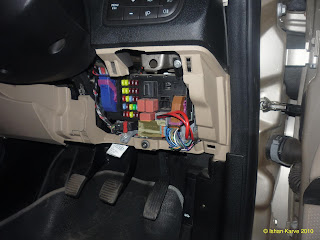
CAN Bus Location in Fiat Linea


Tyco/AMP produces the in-car (female) side of the plug as part numbers 179631 or 348822, and both use the same pins, either P/N 776001 or 1827012. Molex has a similar offering; the pins are P/N 50420, and the housings are 51115 (with a 51117 retainer) and 51116 (with a 51118 retainer). Delphi/Packard's part numbers are 11210250 for the housing and 12129373, 12129484, 13525297, and 15317769 for the pins (female Metri-Pack 150).
The client-side connection is pretty ubiquitous. The Molex P/Ns are 57964 for the pins, and 68503 for the housing. Delphi shows 12110252 as the P/N for the housing, and 12040993, 12047581, 12059894, 12092165, 12110502, 12160811, 15305307, or 15326725 for the pins (male Metri-Pack 150), depending on the size you need.
OBD-II Port Details

CAN Bus Location in Fiat Linea


Interface Board
Test Setup
Hardware:- 18F4550 , MCP2551 , MCP2515, 2x20MHz Crystals, 220nf Cap, 4x10KOhms, Headers
Development : CCS Compiler, MPLAB IDE, PICKIT3 Programmer and Debugger, USB-RS232 FTDI Breakout Board
Loopback Test Program to verify especially MCP2515 CAN Trans-receiver (RS232 MODE)
Connection Matrix as follows
| PIC18F4550 | MCP2515 |
| PIN NO 27 (D4) SPP4 | PIN NO (16) CS |
| PIN NO 33 (B0) SDI | PIN NO (15)SO |
| PIN NO 26 (C7) SDO | PIN NO (14)SI |
| PIN NO 34 (B1) SCK | PIN NO (13)CLK |
| PIN NO 16(C1) CCP2 | PIN NO (12)INT |
Code Sample:
#include <18F4550.h>
#fuses HSPLL,NOWDT,NOPROTECT,NOLVP,NODEBUG,USBDIV,PLL5,CPUDIV1,VREGEN
#use delay(clock=48000000)
#use rs232(baud=9600, xmit=PIN_E1,rcv=PIN_E2)
//not used only for diagnostic
#define LED    PIN_D1

// These connections are for the Microchip MCP2510 Dev. board
#define EXT_CAN_CS   PIN_D4
#define EXT_CAN_SO   PIN_B0
#define EXT_CAN_SI   PIN_C7
#define EXT_CAN_SCK  PIN_B1

#include <can-mcp251x.c>

void main(void)
{
int32 can_id;
int can_data[8];
int can_length, counter;
struct rx_stat rxstat;

puts("Can Sample");

can_init();
puts("Can init done");

can_set_mode(CAN_OP_LOOPBACK);
puts("Loopback mode set");

counter = 0;
puts("Starting");

can_data[0] = 0x55;

while(1)
{
    if(kbhit())
      {
       getch();

       if(can_putd(42, can_data, 1, 3, TRUE, FALSE))
             puts("tx ok");

       while(!can_kbhit());

       if(can_getd(can_id, &can_data[0], can_length, rxstat))
             puts("rx ok");

       counter++;
    }
}

}
Loopback Test Program to verify especially MCP2515 CAN Trans-receiver (USB CDC)
#include <18F4550.h>
#fuses HSPLL,NOWDT,NOPROTECT,NOLVP,NODEBUG,USBDIV,PLL5,CPUDIV1,VREGEN
#use delay(clock=48000000)
#use rs232(baud=9600, xmit=PIN_D1,rcv=PIN_E2)
//not used only for diagnostic
#define LED    PIN_D1

// These connections are for the Microchip MCP2510 Dev. board
#define EXT_CAN_CS   PIN_D4
#define EXT_CAN_SO   PIN_B0
#define EXT_CAN_SI   PIN_C7
#define EXT_CAN_SCK  PIN_B1

#include <can-mcp251x.c>
#include <usb_cdc.h>

void main(void)
{
char c;
int32 can_id;
int can_data[8];
int can_length, counter;
struct rx_stat rxstat;

puts("Can Sample");

can_init();
puts("Can init done");

can_set_mode(CAN_OP_LOOPBACK);
puts("Loopback mode set");

counter = 0;
puts("Starting");

can_data[0] = 0x55;
usb_init_cs();
while(1)
{
    usb_task();

    if(usb_cdc_kbhit())
      {
       c=usb_cdc_getc();

       if(can_putd(42, can_data, 1, 3, TRUE, FALSE))
            printf(usb_cdc_putc,"tx ok");

       while(!can_kbhit());

       if(can_getd(can_id, &can_data[0], can_length, rxstat))
              printf(usb_cdc_putc,"rx ok");

       counter++;
    }
}

}

This is really cool. I'm actually considering doing the same for my car. Could you possibly provide a circut diagram to go along with that picture? I'm seriously lacking on some knowledge considering I'm only a sophomore at Rutgers but I'm trying to learn as much as possible.
ReplyDelete