#include <16f628a.h>
#fuses INTRC_IO, NOWDT, BROWNOUT,  NOLVP
#use delay(internal=4MHz)
#define LED  PIN_B4
#define IR  PIN_B3
#define RELAY1  PIN_A2
#define RELAY2  PIN_A3
#define RELAY3  PIN_B1
#define RELAY4  PIN_B2

/* TIMER0 configuration */
#define TIMER0_CONFIG   RTCC_INTERNAL | RTCC_DIV_1

/* Interrupt rate:                     */
/* 4/4000000*65536*1 = 0.256 ms       */
/*                                     */
/*     Start: 3.0 ms (ignored)         */
/*     "1":   1.8 ms (225)           */
/*     "0":   1.2 ms  (150)           */
/*

*/
#define ONE_MIN  190
#define ONE_MAX  400
#define ZERO_MIN 10
#define ZERO_MAX 185

short rly1,rly2,rly3,rly4,state;

/* irframes[0] (start) will be garbage, ignore it...  */
int16 irframes[13];
int8 ircount = 0;
int1 irdone = FALSE;


#int_ccp1
void ext_ccp1() {
  if (irdone) return;
  irframes[ircount++] = get_timer0();
  if (ircount >= 13)
    irdone = TRUE;
  set_timer0(0);
  enable_interrupts(INT_TIMER0);
//#output_bit(LED,1);delay_ms(1);output_bit(LED,0);delay_ms(1);
}


#int_timer0
void timer0_isr() {
  disable_interrupts(INT_TIMER0);
}


#separate
int1 decode_ir(int8 &addr, int8 &cmd) {
  int8 i;
  int8 mask;
  int8 bits[13];

  addr = 0;
  cmd = 0;

  for (i=1; i<=12; i++) {
    if ((ONE_MIN <= irframes[i]) && (irframes[i] <= ONE_MAX))
      bits[i] = 0x01;
    else
      if ((ZERO_MIN <= irframes[i]) && (irframes[i] <= ZERO_MAX))
        bits[i] = 0x00;
      else        // Error
        return FALSE;
  }

  mask = 0x01;
  for (i=1; i<=7; i++) {
    if (bits[i])
      cmd = cmd | mask;
    mask <<= 1;
  }

  mask = 0x01;
  for (i=8; i<=12; i++) {
    if (bits[i])
      addr = addr | mask;
    mask <<= 1;
  }

  return TRUE;
}


void start_ir() {
  memset(irframes, 0x00, sizeof(irframes));
  ircount = 0;
  irdone = FALSE;
}


void led_blink(int i)
{
int j;
for (j=0;j> Tuesday, November 22, 2011
Code Dump: Remote Controlled 4 Channel Relay
Saturday, November 19, 2011
MSP430 : Hello World LED Blink program
This is my first program to blink all LEDs connected on PORT3 of MSP430 onboard TI MSP430FR5739 experimenters board.
/******************************************************************
 * This is my first project on my MSP430FR5739 experimenter board.
 * In this project I will attempt to blink all onboard LEDs which
 * are connected to Port 3.
 * Pseudo code as follows
 * 1. Initialise port 3 as an output port.
 * 2. Set Port 3 to digital low.
 * 3. Initialise Loop
 * 4. Set Port 3 to Digital High
 * 5. Delay (Hold State).
 * 6. Set Port 3 to Digital Low
 * 7. Delay (Hold State).
 * 8. Loop End
*******************************************************************/
#include "msp430fr5739.h"
#include "FR_EXP.h"
void delay(void);

void main(void) {
 WDTCTL = WDTPW + WDTHOLD;
 P3DIR = 0xFF;  // initialize Port 3 as output by ensuring bit 0 is 0.

 for (;;) {  // Initialise loop
  P3OUT=0xff;
  __delay_cycles(100000); // SW Delay of 10000 cycles at 1Mhz
  P3OUT=0x00;
  __delay_cycles(100000); // SW Delay of 10000 cycles at 1Mhz

  }//for loop
} // main


void delay(void) {
 int i;
 for (i=0; i<0xFF; i++) {
 }
} // delay
Thursday, July 28, 2011
Simple Script to Download epaper from The Hindu
#!/bin/bash
#ishan dot karve at gmail dot com
#
#Script to download epaper from Hindu
#No more subscription .. pls donate the money to Prime Ministers Welfare Fund
#As always /// Its free to use...
#Get user to select edition
edition_choice=([0]=101 [1]=102 [2]=103 )
edition_name=([0]=Chennai [1]=Hyderabad [2]=Delhi )
echo "Hindu epaper editions are"
echo "-------------------------------------------------"
echo "0. Chennai"
echo "1. Hyderabad"
echo "2. Delhi"
echo "-------------------------------------------------"
while true; do
    read -p "Enter edition you wish to selec[0-2]: " ed
    case $ed in
       [012])
 echo "Thanks."
 break;;
        * ) echo "Please select the correct numeric serial.";;
    esac
done
#spider the selected edition using wget to estimate number of pages
#define max incremental page limit
max_spider=100
echo "Estimating number of pages in ${edition_name[ed]} edition"
#start spider for main editon
 for ((  j = 1 ;  j <= $max_spider;  j++  ))
    do
      #prepend zero to single digits
      pageno=`printf "%03d" $j`
      echo "Searching for Page $pageno"
      I_FILE="http://epaper.thehindu.com/pdf/`date +%Y`/`date +%m`/`date +%d`/`date +%Y``date +%m``date +%d`A_$pageno${edition_choice[ed]}.pdf"
 debug=`wget --spider $I_FILE 2>&1`

 echo $debug
      if [[ $debug =~ .*link!!!.* ]]
      then
      break
      fi
done
clear
#decrement counter
(( j = j - 1 ))
npages_A=$j
echo "Estimating number of pages in ${edition_name[ed]} edition supplement"


#start spider for newapaper supplement
 for ((  j = 1 ;  j <= $max_spider;  j++  ))
    do
      #prepend zero to single digits
      pageno=`printf "%03d" $j`
      echo "Searching for Page $pageno"
      I_FILE="http://epaper.thehindu.com/pdf/`date +%Y`/`date +%m`/`date +%d`/`date +%Y``date +%m``date +%d`B_$pageno${edition_choice[ed]}.pdf"
 debug=`wget --spider $I_FILE 2>&1`

 echo $debug
      if [[ $debug =~ .*link!!!.* ]]
      then
      break
      fi
done
clear
#decrement counter
(( j = j - 1 ))
npages_B=$j

ty_dir="$HOME/Desktop/hindu_${edition_name[ed]}_`date +%d``date +%m``date +%Y`"
#mkdir to store individual pages
mkdir $ty_dir
echo "Please be patient..Bandwidth intensive operation starts..;-)"
echo "Downloading Main Paper .. total $npages_A pages"
    for ((  i = 1 ;  i <= npages_A;  i++  ))
    do
      #prepend zero to single digits
      pageno=`printf "%03d" $i`
      echo "Downloading Page $pageno"
      O_FILE="$ty_dir/A$pageno.pdf"
      I_FILE="http://epaper.thehindu.com/pdf/`date +%Y`/`date +%m`/`date +%d`/`date +%Y``date +%m``date +%d`A_$pageno${edition_choice[ed]}.pdf"
      wget -q -O $O_FILE $I_FILE

    done

echo "Downloading Supplement .. total $npages_B pages"

  for ((  i = 1 ;  i <= npages_B;  i++  ))
    do
      #prepend zero to single digits
      pageno=`printf "%03d" $i`
      echo "Downloading Page $pageno"
      O_FILE="$ty_dir/B$pageno.pdf"
      I_FILE="http://epaper.thehindu.com/pdf/`date +%Y`/`date +%m`/`date +%d`/`date +%Y``date +%m``date +%d`B_$pageno${edition_choice[ed]}.pdf"
      wget -q -O $O_FILE $I_FILE

    done


echo "Combining all pages into a single pdf document"
#combine multiple pdf files
gs -dNOPAUSE -sDEVICE=pdfwrite -sOUTPUTFILE=The_Hindu_${edition_name[ed]}_`date +%d``date +%b``date +%Y`.pdf -dBATCH $ty_dir/*.pdf
#empty directory
rm $ty_dir/*.*
#remove directory
rmdir $ty_dir
Copy the script to your Linux desktop
go to command prompt using terminal
type following commands
cd ~/Desktop
chmod +x thehindu.sh
./thehindu.sh
Tuesday, July 19, 2011
Simple Script to Download epaper from Mid-Day
#!/bin/bash
#ishan dot karve at gmail dot com
#Script to download epaper from mid-day.com
#As always /// Its free to use...
#Get user to select edition
edition_choice=([0]=mumbai [1]=delhi [2]=bangalore [3]=pune)
edition_abbr=([0]=md-mn [1]=md-dn [2]=md-bn [3]=md-pn)
echo "Mid-Day epaper editions are"
echo "-------------------------------------------------"
echo "0. Mumbai"
echo "1. Delhi"
echo "2. Bangalore"
echo "3. Pune"
echo "-------------------------------------------------"
while true; do
    read -p "Enter edition you wish to selec[0-9]: " ed
    case $ed in
       [0123])
 echo "Thanks."
 break;;
        * ) echo "Please select the correct numeric serial.";;
    esac
done
#Get user to input starting page
read -p "Please enter the starting page you wish to download from?" strt_pg
#Get user to input ending page
read -p "Please enter the ending page you wish to download?" end_pg
while true; do
    read -p "Do you wish download pages $strt_pg to $end_pg? [Y/N]" yn
    case $yn in
        [Yy]* )
    for ((  i = $strt_pg ;  i <= end_pg;  i++  ))
    do
      echo "Downloading Page $i"

      I_FILE="http://epaper2.mid-day.com/DRIVE/${edition_choice[ed]}/`date +%d``date +%m``date +%Y`/epaperpdf/19072011-${edition_abbr[ed]}-$i.pdf"
      wget $I_FILE
    done
     break;;
        [Nn]* ) exit;;
        * ) echo "Please answer yes or no.";;
    esac
done
How to get it running
Copy the script to your Linux desktop
go to command prompt using terminal
type following commands
cd ~/Desktop
chmod +x milk_day.sh
./milk_day.sh
Simple Script to Download epaper from Indian Express
#!/bin/bash
# ishan dot karve at gmail dot com
#Script to download epaper from indian express
#As always /// Its free to use...
clear
curl -s http://epaper.indianexpress.com > /tmp/editions
temp1=$(sed -nr 's/(.*)max-height:none;" src="?([^ ">]*).*/\2\n\1/; T; P; D;' /tmp/editions)
temp2=$(sed -n -e 's/.*<span class="caption">\(.*\)<\/span>.*/\1/p' /tmp/editions)
editions=($(echo $temp2 | tr " " "\n"))
editions_link=($(echo $temp1 | tr " " "\n"))
echo "Following ${#editions[*]} Editions available for download"
count=0
for i in "${editions[@]}"
do
 echo $count.  $i
 count=$((count+1))
done
while true; do
    read -p "Enter edition you wish to select[0-9]: " ed
    case $ed in
       [0123456789])
echo "Processing..."
break;;
        * ) echo "Please select the correct numeric serial.";;
    esac
done

if [ "$ed" -ge "${#editions[*]}" ]
then
echo "Please select proper edition. Please try again. Bye."
exit 0
fi

links=${editions_link[$ed]}
#grab edition id
edition_id=($(echo $links | cut -d "/" -f4))
#Get user to input starting page
read -p "Please enter the starting page you wish to download from?" strt_pg
#Get user to input ending page
read -p "Please enter the ending page you wish to download?" end_pg
while true; do
    read -p "Do you wish download pages $strt_pg to $end_pg? [Y/N]" yn
    case $yn in
        [Yy]* )
 ty_dir="$HOME/Desktop/ie_day_`date +%d``date +%m``date +%Y`"
 mkdir $ty_dir

 for ((  i = $strt_pg ;  i <= end_pg;  i++  ))
 do
#prepend zero to single digits
      pageno=`printf "%02d" $i`
      echo "Downloading Page $pageno"
      O_FILE="$ty_dir/$pageno.pdf"
      I_FILE="http://epaper.indianexpress.com/pdf/get/$edition_id/$i"
   wget -O $O_FILE $I_FILE
 done
  break;;
        [Nn]* ) exit;;
        * ) echo "Please answer yes or no.";;
    esac
done
#combine multiple pdf files
gs -dNOPAUSE -sDEVICE=pdfwrite -sOUTPUTFILE=ie_`date +%d``date +%m``date +%Y`.pdf -dBATCH $ty_dir/*.pdf
#empty directory
rm $ty_dir/*.*
#remove directory
rmdir $ty_dir
How to get it running
Copy the script to your Linux desktop
go to command prompt using terminal
type following commands
cd ~/Desktop
chmod +x milk_express.sh
./milk_express.sh
Tuesday, July 12, 2011
Simple Script to Download epaper from Times of India
#!/bin/bash
#Written for a friend in need
#Script to download epaper from indiatimes.com
#As always /// Its free to use...
#Get user to select edition
edition_choice=([0]=TOIM [1]=CAP [2]=TOIB [3]=TOIKM [4]=TOICH [5]=TOIPU [6]=TOIA [7]=TOIL [8]=TOIJ [9]=TOIH)
echo "Times of India epaper editions are"
echo "-------------------------------------------------"
echo "0. Mumbai"
echo "1. Delhi"
echo "2. Bangalore"
echo "3. Kolkata"
echo "4. Chennai"
echo "5. Pune"
echo "6. Ahmedabad"
echo "7. Lucknow"
echo "8. Jaipur"
echo "9. Hyderabad"
echo "-------------------------------------------------"
while true; do
    read -p "Enter edition you wish to selec[0-9]: " ed
    case $ed in
       [0123456789])
 echo "Thanks."
 break;;
        * ) echo "Please select the correct numeric serial.";;
    esac
done
#Get user to input starting page
read -p "Please enter the starting page you wish to download from?" strt_pg
#Get user to input ending page
read -p "Please enter the ending page you wish to download?" end_pg
while true; do
    read -p "Do you wish download pages $strt_pg to $end_pg? [Y/N]" yn
    case $yn in
        [Yy]* )
    for ((  i = $strt_pg ;  i <= end_pg;  i++  ))
    do
      echo "Downloading Page $i";
      I_FILE="http://epaper.timesofindia.com/Repository/${edition_choice[ed]}/`date +%Y`/`date +%m`/`date +%d`/${edition_choice[ed]}_`date +%Y`_`date +%-m`_`date +%d`_$i.pdf"
      wget $I_FILE
    done
     break;;
        [Nn]* ) exit;;
        * ) echo "Please answer yes or no.";;
    esac
done
How to get it running
Copy the script to your Linux desktop
go to command prompt using terminal
type following commands
cd ~/Desktop
chmod +x test_1.sh
./test_1.sh
14 Jul 2011 0026 : Script updated to reflect various editions....
Saturday, July 9, 2011
Microcontroller based Pump Controller
Updates:-
- 28 Jun 11: I cant help but thank the kind guys at Texas Instruments. I cant believe my eyes, they have shipped me a sample of their instrumentation amplifier. Thats would help me simplify my input block. Thanks u guys… You rock.
- 01 Jul 11: Received Sample. Waiting for Farnell guys to ship my pressure sensors…
- 07 Jul 11 : Received Pressure sensors.
This project will describe building of a Pump control system. The requirement primarily arose to satiate the requirements of my parents, who have to manually switch on the pump every day morning and switch it off and continuously monitor the tank for overflow. So I have taken up the challenge onto myself...
However I would be ungrateful, I do not acknowledge the inputs I received after reading Kayne Richens blog post.
This blog is progressive ; hence will get updated as things progress.....
Lets me see how do things unfold...
Basic Design Objectives:-
Lets me see how do things unfold...
Basic Design Objectives:-
- Should be cheap and affordable.
- Should be as automated as possible requiring minimal user supervision.
- Should have a user-friendly MMI.
- Prevent water and electricity wastage.
- Erratic water supply timings.
- Non scheduled Electrical Load shedding .
- High head of water tank.
- Intelligent control system.

System Blocks Functions:-
Input Block:-
| Input Description | Sensor Type | Micro-controller Input |
|---|---|---|
| Sense Tank Capacity | Differential Pressure Sensor | Analog |
| Sense Electricity Availability | Optocoupler | Digital/Interrupt |
| Sense Time | RTC | Digital |
| Sense Input Water Supply Availability | Differential Pressure Sensor | Analog |
Output Block:-
| Output Description | Transducer Type | Micro-controller Output |
|---|---|---|
| Motor On/Off | Solid State Relay | Digital |
| Valve Solenoid On/Off | Relay | Digital |
| Alarm | Buzzer | Analog |
Mathematics for Selecting Differential Pressure Sensor:-
Why Differential Pressure Sensor?
A differential pressure sensor will eliminate variation in pressure due to changes in atmospheric pressure.
Mathematics
Capacity of Water Tank = 500 Lt
Water Tank Head = 30 Ft = 9.144 Mt = 914.4 Cm
Average Ambient Temperature = 25 deg Celcius
Specific Gravity of Tap water=0.997gm per cubic cm = 997Kg per cubic meter
Dia of Discharge Pipe=1/2 in = 1.27 Cm=0.0127 M
Pressure exerted at Base of Building by a column of Water at height
P = h * rho * g
where
P = Pressure
h = height of liquid column (2000 mm = 2m)
rho = Density of water (1000 kg/m^3)
g = Acceleration due to gravity (9.81 m/s^2)
P = Pressure
h = height of liquid column (2000 mm = 2m)
rho = Density of water (1000 kg/m^3)
g = Acceleration due to gravity (9.81 m/s^2)
P=9.14 x 997x 9.81 = 89394.4098 Pascals = 89.39kPa = 89.4 kPa (approx)
Similarly Pressure at Rooftop at the base of tank itself
P=1.5 x 997x 9.81 =14670.855 Pascals =14.67kPa = 14.7 kPa (approx)
Selected Sensor : Freescale Differential Pressure Sensor MPX2100DP 0-100 kPa
Selection of MCU:-
Family : Microchip PIC
Why : Because I have necessary experience and required development tools.
Max No of ADC Channels Required = 3 (2xpressure Sensor + 1 spare)
No of Interrupts : 02 (Electrical Supply Available & Float Valve)
Digital I/O = 8
Operating Voltage= 5V
SPI Required = Yes (For Interfacing RTC)
MCU Selected = 16F876A or 16F877A Why? Because I already have!
Design of Pressure Sensor Amplifier:-
Design Guide/Reference : -
- Op Amps for Everyone Design Guide.
Amplifier Design Objective : The output span of the transducer must be matched to the input span of the ADC to achieve optimum performance.
Mathematics for Amplifier Design
Mathematics for Amplifier Design
Span and Offset Characteristics at 10v,15v & 5V Excitation Voltage. As sensor is ratio-metric the the values are scaled for.
MPX2100DP
| Excitation Voltage | Min Span (mV) | Max Span (mV) | Min. Offset (mV) | Max Offset (mV) |
|---|---|---|---|---|
| 10V | 38.5 | 40 | -1 | 1 |
| 15V (scaled) | 57.75 | 60 | -1.5 | 1.5 |
| 5V (scaled) | 19.25 | 20 | -0.5 | 0.5 |
| 9V(scaled) | 34.65 | 3.6 | -0.9 | 0.9 |
MPX2010DP
| Excitation Voltage | Min Span (mV) | Max Span (mV) | Min. Offset (mV) | Max Offset (mV) |
|---|---|---|---|---|
| 10V | 24 | 26 | -1 | 1 |
| 15V (scaled) | 36 | 39 | -1.5 | 1.5 |
| 5V (scaled) | 12 | 13 | -0.5 | 0.5 |
| 9V(scaled) | 21.6 | 23.4 | -0.9 | 0.9 |
Desired Amplified Span and Offset
Desired Offset= 0.5V
Desired Span = 5V
Gain Range & Offset Calculation
Maximum Gain =Desired Span (V)
Sensor’s Minimum Span
Desired Span = 5V
| Excitation Voltage | Maximum Gain (MPX2100DP) | Maximum Gain (MPX2010DP) |
| 10V | =5/38.5 = 129.8 = 130 | 208 |
| 15V | =5/57.75 = 86.58 = 87 | 139 |
| 5V | =5/19.25 = 259.75 = 260 | 417 |
| 9V | =5/34.65=144.300=144 | 231 |
Since Texas Instruments was kind to ship me samples of their instrumentation amplifiers, I would be basing my calculations on same. There is no rocket science involved since the datasheet is fairly self explanatory and the instrumentation amplifier itself requires only one external component for gain adjustment.
Texas Instruments was generous in mailing following samples to me
INA126, INA128,INA122,INA2126
I would be using INA126 amplifier for testing purpose
Brief description about INA126 ..”The INA126 and INA2126 are precision instrumentation amplifiers for accurate, low noise differential signal acquisition. Theirtwo-op-amp design provides excellent performance with very low quiescent current (175µA/channel). This, combined with awide operating voltage range of ±1.35V to ±18V, makes them ideal for portable instrumentation and data acquisition systems. Gain can be set from 5V/V to 10000V/V with a single external resistor. Laser trimmed input circuitry provides low offset voltage (250µV max), low offset voltage drift (3µV/°C max) and excellent common-mode rejection.”
Gain calculation formulae
| Instr Amplifier | Gain Formula |
| INA 122 | G=5+200kΩ RG |
| INA 126 | G=5+80kΩ RG |
| INA 128 | G=1+50kΩ RG |
RG (IN OHMS)values at Max Gain. Values in (brackets) indicate nearest standard resistor values.
MPX2100DP
| Instr. Amplifier | 10V | 15V | 5V | 9V |
| INA 122 | 1602 Ω (1.6KΩ) | 2452Ω(2.4KΩ) | 785Ω (750Ω) | 1439Ω(1.5K) |
| INA 126 | 641Ω (620Ω) | 981Ω (1kΩ) | 584Ω (560Ω) | 576Ω(560Ω) |
| INA 128 | 388Ω (390Ω) | 548Ω (560Ω) | 193Ω (180Ω) | 347Ω(360Ω) |
MPX2010DP
| Instr. Amplifier | 10V | 15V | 5V | 9V |
| INA 122 | 984 Ω (1KΩ) | 1494Ω(1.5KΩ) | 486Ω (470Ω) | 885Ω(820Ω) |
| INA 126 | 393Ω (390Ω) | 598Ω (560kΩ) | 194Ω (200Ω) | 356Ω(360Ω) |
| INA 128 | 241Ω (240Ω) | 363Ω (360Ω) | 120Ω (120Ω) | 214Ω(200Ω) |
Amplifier Interface Design
![\includegraphics[scale=0.500000]{ckt8.1.1.ps}](https://lh3.googleusercontent.com/blogger_img_proxy/AEn0k_vta16IVCTUGO7yo0uGJpZH6r-RHQphS1S43mjg7bky129aYvtu7Rhko1j1P4VWeuwapFuZ7VbG1RvFm3R24c5NkyfyJ4GHqmh14CwP4UT6uQC6=s0-d)
In the MPX sensor, each of the resistors in the bridge is an active strain gage, so this design illustration is applicable for the amplifier design.

Test Schematic

3D PCB Render (Using Diptrace)

Tuesday, June 28, 2011
DIY CAN Bus Analyzer for Fiat Linea (Incomplete!!!Being Developed ….)
OBD-II Port Details
Tyco/AMP produces the in-car (female) side of the plug as part numbers 179631 or 348822, and both use the same pins, either P/N 776001 or 1827012. Molex has a similar offering; the pins are P/N 50420, and the housings are 51115 (with a 51117 retainer) and 51116 (with a 51118 retainer). Delphi/Packard's part numbers are 11210250 for the housing and 12129373, 12129484, 13525297, and 15317769 for the pins (female Metri-Pack 150).
The client-side connection is pretty ubiquitous. The Molex P/Ns are 57964 for the pins, and 68503 for the housing. Delphi shows 12110252 as the P/N for the housing, and 12040993, 12047581, 12059894, 12092165, 12110502, 12160811, 15305307, or 15326725 for the pins (male Metri-Pack 150), depending on the size you need.
OBD-II Port Details

CAN Bus Location in Fiat Linea


Interface Board

Test Setup
Hardware:- 18F4550 , MCP2551 , MCP2515, 2x20MHz Crystals, 220nf Cap, 4x10KOhms, Headers
Development : CCS Compiler, MPLAB IDE, PICKIT3 Programmer and Debugger, USB-RS232 FTDI Breakout Board
Loopback Test Program to verify especially MCP2515 CAN Trans-receiver (RS232 MODE)
Connection Matrix as follows
| PIC18F4550 | MCP2515 |
| PIN NO 27 (D4) SPP4 | PIN NO (16) CS |
| PIN NO 33 (B0) SDI | PIN NO (15)SO |
| PIN NO 26 (C7) SDO | PIN NO (14)SI |
| PIN NO 34 (B1) SCK | PIN NO (13)CLK |
| PIN NO 16(C1) CCP2 | PIN NO (12)INT |
Code Sample:
#include <18F4550.h>
#fuses HSPLL,NOWDT,NOPROTECT,NOLVP,NODEBUG,USBDIV,PLL5,CPUDIV1,VREGEN
#use delay(clock=48000000)
#use rs232(baud=9600, xmit=PIN_E1,rcv=PIN_E2)
//not used only for diagnostic
#define LED    PIN_D1

// These connections are for the Microchip MCP2510 Dev. board
#define EXT_CAN_CS   PIN_D4
#define EXT_CAN_SO   PIN_B0
#define EXT_CAN_SI   PIN_C7
#define EXT_CAN_SCK  PIN_B1

#include <can-mcp251x.c>

void main(void)
{
int32 can_id;
int can_data[8];
int can_length, counter;
struct rx_stat rxstat;

puts("Can Sample");

can_init();
puts("Can init done");

can_set_mode(CAN_OP_LOOPBACK);
puts("Loopback mode set");

counter = 0;
puts("Starting");

can_data[0] = 0x55;

while(1)
{
    if(kbhit())
      {
       getch();

       if(can_putd(42, can_data, 1, 3, TRUE, FALSE))
             puts("tx ok");

       while(!can_kbhit());

       if(can_getd(can_id, &can_data[0], can_length, rxstat))
             puts("rx ok");

       counter++;
    }
}

}
Loopback Test Program to verify especially MCP2515 CAN Trans-receiver (USB CDC)
#include <18F4550.h>
#fuses HSPLL,NOWDT,NOPROTECT,NOLVP,NODEBUG,USBDIV,PLL5,CPUDIV1,VREGEN
#use delay(clock=48000000)
#use rs232(baud=9600, xmit=PIN_D1,rcv=PIN_E2)
//not used only for diagnostic
#define LED    PIN_D1

// These connections are for the Microchip MCP2510 Dev. board
#define EXT_CAN_CS   PIN_D4
#define EXT_CAN_SO   PIN_B0
#define EXT_CAN_SI   PIN_C7
#define EXT_CAN_SCK  PIN_B1

#include <can-mcp251x.c>
#include <usb_cdc.h>

void main(void)
{
char c;
int32 can_id;
int can_data[8];
int can_length, counter;
struct rx_stat rxstat;

puts("Can Sample");

can_init();
puts("Can init done");

can_set_mode(CAN_OP_LOOPBACK);
puts("Loopback mode set");

counter = 0;
puts("Starting");

can_data[0] = 0x55;
usb_init_cs();
while(1)
{
    usb_task();

    if(usb_cdc_kbhit())
      {
       c=usb_cdc_getc();

       if(can_putd(42, can_data, 1, 3, TRUE, FALSE))
            printf(usb_cdc_putc,"tx ok");

       while(!can_kbhit());

       if(can_getd(can_id, &can_data[0], can_length, rxstat))
              printf(usb_cdc_putc,"rx ok");

       counter++;
    }
}

}
Saturday, June 25, 2011
Large Digit LCD Clock
I generally tend to spend a lot of time working on my PC, not realising what the time it is. A bit of ponder made me realise that I did not have a clock in my room (Thats the Xcuse!!).. Clock in the deskbar/panel/Taskbar is so Uncool.. So I decided to make a custom made digital clock.
An immediate rummaging of my component inventory revealed that I had the necessary gear to accomplish the task..
So here's the part list:-
- PIC 16F628A
- RTC DS1302
- HD44780 Compatible 20x4 LCD Display
- Rotary/Quadrature Encoder
- Resistors
- Capacitors
- Diodes
- LM7805
- Prototyping Board
- Trimpot 10K
- Patience
Development Platform: MPLAB using CCS C Compiler and a PICKIT3 Programmer/Debugger.
Cool Factor: No Buttons for Menu. Only a single Quadrature Rotary Encoder accomplishes all required menu operations.
Schematic

End Product
 |
| End Product poorly mounted ! |
 |
| Time is 17:19 |
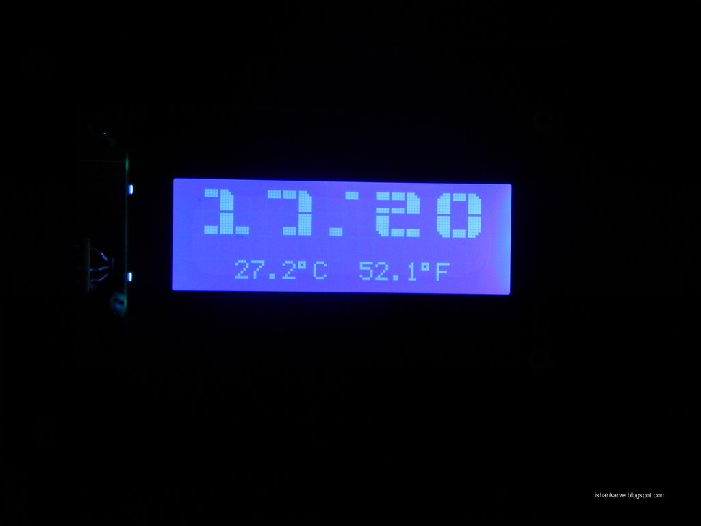 |
| Still working after three minutes...... Gr8! |
large_lcd.h
#include <16f628a.h>
#fuses INTRC_IO, NOWDT, BROWNOUT,  NOLVP
#use delay (internal=4MHz)

//=======================
#include "flex_lcd.h"
#include "ds1302.h"
#include "ds18b20.h"
//===================================

//========================================MENU FLAGS==========================================
//menu flags/value. default state/value of all flags is 0
short blink_flag=0;
int menu_digit_flag=0;    //1 is hour; 2 is minute ;0 is normal modde
int clock_mode=0;//0 is normal ; 1 is menu mode (blinking display); 2 is edit mode
//============================================================================================
byte hour,minute,second,day,month,year,weekday;
 int8 b1, b2, b3, b4;
byte HH,MM;

//for rotary encoder
#define CH_A    PIN_A4
#define CH_B    PIN_A3
#define button    PIN_A2

int encoder0Pos = 0;
int encoder0PinALast = 0;
int n = 0;

void read_encoder(){
int MAX=9; int MIN=0;
if (menu_digit_flag==1){MAX=23;}//hours
if (menu_digit_flag==2) {MAX=59;}//minutes
n = input(CH_B);
   if ((encoder0PinALast == 0) && (n == 1)) {
    lcd_gotoxy(1,1);
    printf(lcd_putc,"                   ");
    lcd_gotoxy(1,2);
    printf(lcd_putc,"                   ");

     if (input(CH_B) == 0) {
       encoder0Pos--;
     } else {
       encoder0Pos++;
     }

    }
   encoder0PinALast = n;


if(encoder0Pos>MAX){encoder0Pos=0;}
if(encoder0Pos<MIN){encoder0Pos=0;}


}
void display_number(int num){
int digit1,digit2;
if (num<=99){
digit1=num/10;
digit2=num%10;
show_num(digit1);
x_pos_state=x_pos_state+4;
show_num(digit2);
x_pos_state=1;
}
}


adj_hour()
{
x_pos_state=2;
read_encoder();
HH=encoder0Pos;
display_number(HH);

}


adj_minute()
{
x_pos_state=13;
read_encoder();
MM=encoder0Pos;
display_number(MM);

}

set_time(){
//set rtc time
rtc_set_datetime(day,month,year,weekday,HH,MM);
//reset all flags to normal state

}
//=============================
#include <button_interrupt.c>
//=============================
void main()
{


    // Setup timer2 to int every 1ms
  setup_timer_2(T2_DIV_BY_4,125,5);
  enable_interrupts(INT_TIMER2);
  enable_interrupts(GLOBAL);

  // Start counting now
  Miliseconds = 0;


// The lcd_init() function should always be called once,
// near the start of your program.
lcd_init();
lcd_load_custom_chars();
rtc_init();

// Clear the LCD.
printf(lcd_putc, "\f");
delay_ms(250);

while(1)
{


    if ((clock_mode==2) && (menu_digit_flag==1)){adj_hour();}
    if ((clock_mode==2) && (menu_digit_flag==2)){adj_minute();}
if (clock_mode<=1){
rtc_get_time( hour, minute, second );
ResetDS1820();
cDataOut = DS1820_SKIP_ROM;
WriteDS1820();
cDataOut = DS1820_CONVERT_T;
WriteDS1820();
WaitForConversion();
ResetDS1820();
cDataOut = DS1820_SKIP_ROM;
WriteDS1820();
cDataOut = DS1820_READ_SCRATCHPAD;
WriteDS1820();
ReadDS1820();
iTemperature = iDataIn / 2;
lcd_gotoxy(4,4);
printf ( lcd_putc, "%3.1w%cC  %3.1w%cF   ", iTemperature, DEGREE_SYM, ( ( 9 * iTemperature ) / 5 ) + 32, DEGREE_SYM  );

x_pos_state=2;
rtc_get_time( hour, minute, second );
b1=hour;
b2=minute;
if (b3!=b1){clearnumber(2);clearnumber(4);b3=b1;}
if (b4!=b2){clearnumber(13);clearnumber(17);b4=b2;}
display_number(hour);
x_pos_state=10;
if (second%2==0){custom_dah();clearnumber(10);}
if (second%2==1){custom_dit();}
x_pos_state=13;
display_number(minute);
}
System_Tick();
Switch_Tasks();


 }

}
flex_lcd.h (modified for large digits)
// Flex_LCD420.c

// These pins are for my Microchip PicDem2-Plus board,
// which I used to test this driver.
// An external 20x4 LCD is connected to these pins.
// Change these pins to match your own board's connections.

#define LCD_DB4   PIN_A1
#define LCD_DB5   PIN_A0
#define LCD_DB6   PIN_A7
#define LCD_DB7   PIN_A6

#define LCD_RS    PIN_B2
#define LCD_RW    PIN_B1
#define LCD_E     PIN_B0

/*
// To prove that the driver can be used with random
// pins, I also tested it with these pins:
#define LCD_DB4   PIN_D4
#define LCD_DB5   PIN_B1
#define LCD_DB6   PIN_C5
#define LCD_DB7   PIN_B5

#define LCD_RS    PIN_E2
#define LCD_RW    PIN_B2
#define LCD_E     PIN_D6
*/

// If you want only a 6-pin interface to your LCD, then
// connect the R/W pin on the LCD to ground, and comment
// out the following line.  Doing so will save one PIC
// pin, but at the cost of losing the ability to read from
// the LCD.  It also makes the write time a little longer
// because a static delay must be used, instead of polling
// the LCD's busy bit.  Normally a 6-pin interface is only
// used if you are running out of PIC pins, and you need
// to use as few as possible for the LCD.
//#define USE_RW_PIN   0


// These are the line addresses for most 4x20 LCDs.
#define LCD_LINE_1_ADDRESS 0x00
#define LCD_LINE_2_ADDRESS 0x40
#define LCD_LINE_3_ADDRESS 0x14
#define LCD_LINE_4_ADDRESS 0x54

// These are the line addresses for LCD's which use
// the Hitachi HD66712U controller chip.
/*
#define LCD_LINE_1_ADDRESS 0x00
#define LCD_LINE_2_ADDRESS 0x20
#define LCD_LINE_3_ADDRESS 0x40
#define LCD_LINE_4_ADDRESS 0x60
*/


//========================================

#define lcd_type 2   // 0=5x7, 1=5x10, 2=2 lines(or more)

int8 lcd_line;

int x_pos_state=1;


int8 const LCD_INIT_STRING[4] =
{
 0x20 | (lcd_type << 2),  // Set mode: 4-bit, 2+ lines, 5x8 dots
 0xc,                     // Display on
 1,                       // Clear display
 6                        // Increment cursor
 };


//-------------------------------------
void lcd_send_nibble(int8 nibble)
{
// Note:  !! converts an integer expression
// to a boolean (1 or 0).
 output_bit(LCD_DB4, !!(nibble & 1));
 output_bit(LCD_DB5, !!(nibble & 2));
 output_bit(LCD_DB6, !!(nibble & 4));
 output_bit(LCD_DB7, !!(nibble & 8));

 delay_cycles(1);
 output_high(LCD_E);
 delay_us(2);
 output_low(LCD_E);
}

//-----------------------------------
// This sub-routine is only called by lcd_read_byte().
// It's not a stand-alone routine.  For example, the
// R/W signal is set high by lcd_read_byte() before
// this routine is called.

#ifdef USE_RW_PIN
int8 lcd_read_nibble(void)
{
int8 retval;
// Create bit variables so that we can easily set
// individual bits in the retval variable.
#bit retval_0 = retval.0
#bit retval_1 = retval.1
#bit retval_2 = retval.2
#bit retval_3 = retval.3

retval = 0;

output_high(LCD_E);
delay_us(1);

retval_0 = input(LCD_DB4);
retval_1 = input(LCD_DB5);
retval_2 = input(LCD_DB6);
retval_3 = input(LCD_DB7);

output_low(LCD_E);
delay_us(1);

return(retval);
}
#endif

//---------------------------------------
// Read a byte from the LCD and return it.

#ifdef USE_RW_PIN
int8 lcd_read_byte(void)
{
int8 low;
int8 high;

output_high(LCD_RW);
delay_cycles(1);

high = lcd_read_nibble();

low = lcd_read_nibble();

return( (high<<4) | low);
}
#endif

//----------------------------------------
// Send a byte to the LCD.
void lcd_send_byte(int8 address, int8 n)
{
output_low(LCD_RS);

#ifdef USE_RW_PIN
while(bit_test(lcd_read_byte(),7)) ;
#else
delay_us(60);
#endif

if(address)
   output_high(LCD_RS);
else
   output_low(LCD_RS);

 delay_cycles(1);

#ifdef USE_RW_PIN
output_low(LCD_RW);
delay_cycles(1);
#endif

output_low(LCD_E);

lcd_send_nibble(n >> 4);
lcd_send_nibble(n & 0xf);
}
//----------------------------

void lcd_init(void)
{
int8 i;

lcd_line = 1;

output_low(LCD_RS);

#ifdef USE_RW_PIN
output_low(LCD_RW);
#endif

output_low(LCD_E);

// Some LCDs require 15 ms minimum delay after
// power-up.  Others require 30 ms.  I'm going
// to set it to 35 ms, so it should work with
// all of them.
delay_ms(35);

for(i=0 ;i < 3; i++)
   {
    lcd_send_nibble(0x03);
    delay_ms(5);
   }

lcd_send_nibble(0x02);

for(i=0; i < sizeof(LCD_INIT_STRING); i++)
   {
    lcd_send_byte(0, LCD_INIT_STRING[i]);

    // If the R/W signal is not used, then
    // the busy bit can't be polled.  One of
    // the init commands takes longer than
    // the hard-coded delay of 50 us, so in
    // that case, lets just do a 5 ms delay
    // after all four of them.
    #ifndef USE_RW_PIN
    delay_ms(5);
    #endif
   }

}

//----------------------------

void lcd_gotoxy(int8 x, int8 y)
{
int8 address;


switch(y)
  {
   case 1:
     address = LCD_LINE_1_ADDRESS;
     break;

   case 2:
     address = LCD_LINE_2_ADDRESS;
     break;

   case 3:
     address = LCD_LINE_3_ADDRESS;
     break;

   case 4:
     address = LCD_LINE_4_ADDRESS;
     break;

   default:
     address = LCD_LINE_1_ADDRESS;
     break;

  }

address += x-1;
lcd_send_byte(0, 0x80 | address);
}
//----------------------------


//-----------------------------
void lcd_putc(char c)
{
 switch(c)
   {
    case '\f':
      lcd_send_byte(0,1);
      lcd_line = 1;
    //  delay_ms(2);
      break;

    case '\n':
       lcd_gotoxy(1, ++lcd_line);
       break;

    case '\b':
       lcd_send_byte(0,0x10);
       break;

    default:
       lcd_send_byte(1,c);
       break;
   }
}

//------------------------------
#ifdef USE_RW_PIN
char lcd_getc(int8 x, int8 y)
{
char value;

lcd_gotoxy(x,y);

// Wait until busy flag is low.
while(bit_test(lcd_read_byte(),7));

output_high(LCD_RS);
value = lcd_read_byte();
output_low(LCD_RS);

return(value);
}
#endif

const int8 lcd_custom_chars[] =
{
  0b00000111,
  0b00001111,
  0b00011111,
  0b00011111,
  0b00011111,
  0b00011111,
  0b00011111,
  0b00011111,

  0b00011111,
  0b00011111,
  0b00011111,
  0b00000000,
  0b00000000,
  0b00000000,
  0b00000000,
  0b00000000,

  0b00011100,
  0b00011110,
  0b00011111,
  0b00011111,
  0b00011111,
  0b00011111,
  0b00011111,
  0b00011111,

  0b00011111,
  0b00011111,
  0b00011111,
  0b00011111,
  0b00011111,
  0b00011111,
  0b00001111,
  0b00000111,

  0b00000000,
  0b00000000,
  0b00000000,
  0b00000000,
  0b00000000,
  0b00011111,
  0b00011111,
  0b00011111,

  0b00011111,
  0b00011111,
  0b00011111,
  0b00011111,
  0b00011111,
  0b00011111,
  0b00011110,
  0b00011100,

  0b00011111,
  0b00011111,
  0b00011111,
  0b00000000,
  0b00000000,
  0b00000000,
  0b00011111,
  0b00011111,

  0b00011111,
  0b00011111,
  0b00011111,
  0b00011111,
  0b00011111,
  0b00011111,
  0b00011111,
  0b00011111,
};

void lcd_load_custom_chars(void)
{
int8 i;

// Set address counter pointing to CGRAM address 0.
lcd_send_byte(0, 0x40);

// Load custom lcd character data into CGRAM.
// It can only hold a maximum of 8 custom characters.
for(i = 0; i < sizeof(lcd_custom_chars); i++)
   {
    lcd_send_byte(1, lcd_custom_chars[i]);
   }

// Set address counter pointing back to the DDRAM.
lcd_send_byte(0, 0x80);
}

void custom0()
{ // uses segments to build the number 0
  lcd_gotoxy(x_pos_state+0,1); // set cursor to column 0, line 0 (first row)
  lcd_putc(0);  // call each segment to create
  lcd_putc(1);  // top half of the number
  lcd_putc(2);
  lcd_gotoxy(x_pos_state+0, 2); // set cursor to colum 0, line 1 (second row)
  lcd_putc(3);  // call each segment to create
  lcd_putc(4);  // bottom half of the number
  lcd_putc(5);
}

void custom1()
{
  lcd_gotoxy(x_pos_state+0,1);
  lcd_putc(1);
  lcd_putc(2);
  lcd_gotoxy(x_pos_state+0,2);
  lcd_putc(4);
  lcd_putc(7);
  lcd_putc(4);
}

void custom2()
{
  lcd_gotoxy(x_pos_state+0,1);
  lcd_putc(6);
  lcd_putc(6);
  lcd_putc(2);
  lcd_gotoxy(x_pos_state+0, 2);
  lcd_putc(3);
  lcd_putc(4);
  lcd_putc(4);
}

void custom3()
{
  lcd_gotoxy(x_pos_state+0,1);
  lcd_putc(6);
  lcd_putc(6);
  lcd_putc(2);
  lcd_gotoxy(x_pos_state+0, 2);
  lcd_putc(4);
  lcd_putc(4);
  lcd_putc(5);
}

void custom4()
{
  lcd_gotoxy(x_pos_state+0,1);
  lcd_putc(3);
  lcd_putc(4);
  lcd_putc(7);
  lcd_gotoxy(x_pos_state+2, 2);
  lcd_putc(7);
}

void custom5()
{
  lcd_gotoxy(x_pos_state+0,1);
  lcd_putc(3);
  lcd_putc(6);
  lcd_putc(6);
  lcd_gotoxy(x_pos_state+0, 2);
  lcd_putc(4);
  lcd_putc(4);
  lcd_putc(5);
}

void custom6()
{
  lcd_gotoxy(x_pos_state+0,1);
  lcd_putc(0);
  lcd_putc(6);
  lcd_putc(6);
  lcd_gotoxy(x_pos_state+0, 2);
  lcd_putc(3);
  lcd_putc(4);
  lcd_putc(5);
}

void custom7()
{
  lcd_gotoxy(x_pos_state+0,1);
  lcd_putc(1);
  lcd_putc(1);
  lcd_putc(2);
  lcd_gotoxy(x_pos_state+2, 2);
  lcd_putc(7);
}

void custom8()
{
  lcd_gotoxy(x_pos_state+0,1);
  lcd_putc(0);
  lcd_putc(6);
  lcd_putc(2);
  lcd_gotoxy(x_pos_state+0, 2);
  lcd_putc(3);
  lcd_putc(4);
  lcd_putc(5);
}

void custom9()
{
  lcd_gotoxy(x_pos_state+0,1);
  lcd_putc(0);
  lcd_putc(6);
  lcd_putc(2);
  lcd_gotoxy(x_pos_state+2, 2);
  lcd_putc(7);
}

void custom_dit(){
  lcd_gotoxy(x_pos_state+1,1);
  lcd_putc(1);
  lcd_gotoxy(x_pos_state+0,2);
  lcd_putc(4);
}


void custom_dah(){
  lcd_gotoxy(x_pos_state+0,1);
  lcd_putc(1);
  lcd_gotoxy(x_pos_state+1,2);
  lcd_putc(4);

}

void clearnumber(int m)
{ // clears the area the custom number is displayed in
 lcd_gotoxy(m,1);
 printf(lcd_putc,"   ");
 lcd_gotoxy(m,2);
 printf(lcd_putc,"   ");
 }


void show_num(int num){
if (num<=9){
switch (num) {
    case 0:custom0();
           break;
    case 1:custom1();
           break;
    case 2:custom2();
           break;
    case 3:custom3();
           break;
    case 4:custom4();
           break;
    case 5:custom5();
           break;
    case 6:custom6();
           break;
    case 7:custom7();
           break;
    case 8:custom8();
           break;
    case 9:custom9();
           break;

    }

}
}
#define DS1820_DATA_IN_PIN          PIN_B3
#define DS1820_SKIP_ROM             0xCC
#define DS1820_READ_SCRATCHPAD      0xBE
#define DS1820_CONVERT_T            0x44

void ResetDS1820 ( void );
void WriteDS1820 ( void );
void ReadDS1820 ( void );
void WaitForConversion ( void );

#define CLEAR_DISP  0x01
#define DEGREE_SYM  0xdf


static char cShiftBit,cDataOut;
static long iTemperature,iDataIn;


void ResetDS1820 ( void )
    {
    output_low ( DS1820_DATA_IN_PIN );         // low
    delay_us ( 480 );                               // reset pulse width
    output_float ( DS1820_DATA_IN_PIN );          // high
    delay_us ( 480 );                               // presence pulse width
    }

void WriteDS1820 ( void )             // ~70uS per bit
    {
    for ( cShiftBit = 1; cShiftBit <= 8; ++cShiftBit )
        {
        output_low ( DS1820_DATA_IN_PIN );
        delay_us ( 5 );
        output_bit ( DS1820_DATA_IN_PIN, shift_right ( &cDataOut, 1, 0 ) );
        delay_us ( 60 );
        output_float ( DS1820_DATA_IN_PIN );
        delay_us ( 5 );         // recovery time between slots
        }
    //delay_us ( 200 );           // ???
    }

void ReadDS1820 ( void )             // ~70uS per bit
    {
    iDataIn = 0;
    for ( cShiftBit = 1; cShiftBit <= 16; ++cShiftBit )
       {
       output_low ( DS1820_DATA_IN_PIN );
       delay_us ( 5 );
       output_float ( DS1820_DATA_IN_PIN );
       delay_us ( 5 );
       shift_right ( &iDataIn, 2, input ( DS1820_DATA_IN_PIN ) );   // sample bit
       delay_us ( 55 );         // includes recovery time between slots
       }
    ResetDS1820();              // terminate remainder of scratchpad register transmission
    }

void WaitForConversion ( void )             // ~70uS per bit
    {
    while ( TRUE )
       {
       output_low ( DS1820_DATA_IN_PIN );
       delay_us ( 5 );
       output_float ( DS1820_DATA_IN_PIN );
       delay_us ( 5 );
       if ( input ( DS1820_DATA_IN_PIN ) == 1 )   // sample bit
           {
           break;
           }
       delay_us ( 55 );         // includes recovery time between slots
       }
    }
Thursday, June 23, 2011
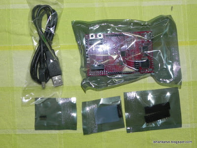
Unboxing TI MSP-EXP430FR5739
While browsing www.hackaday.com I came across TI deal giving 50% off along with free shipping for their TI MSP-EXP430FR5739 Experimenter's Board. At $14, this board is a steal for budding hobbist like me in India. So I decided to try my luck and use the discount coupon shown on Hackaday site and order the board.
To my surprise, the good (I am duty bound to call them so) guys at TI accepted my order and shipped it the same day for delivery at Delhi, India. They shipped the order on Monday 20 Jul 2011 by FedEx and it was delivered to my doorstep by today 23 Jul 2011 noon. 4 days for delivery, I am super impressed.
No sooner than I came home, I saw the box (unboxed) at home and promptly jumped to open it. So here it is for all prospective buyers.. the unboxing of TI MSP-EXP430FR5739.
Main Box (Small Package)


Package Dimensions


Inside Contents

Experimenters' Package


Thats all folks.... I will update you all on progress on the actual usage of the board. Thanks for the read
To my surprise, the good (I am duty bound to call them so) guys at TI accepted my order and shipped it the same day for delivery at Delhi, India. They shipped the order on Monday 20 Jul 2011 by FedEx and it was delivered to my doorstep by today 23 Jul 2011 noon. 4 days for delivery, I am super impressed.
No sooner than I came home, I saw the box (unboxed) at home and promptly jumped to open it. So here it is for all prospective buyers.. the unboxing of TI MSP-EXP430FR5739.
Main Box (Small Package)

Rear View

Package Dimensions


Inside Contents

Experimenters' Package


Thats all folks.... I will update you all on progress on the actual usage of the board. Thanks for the read
Saturday, June 11, 2011
Decoding A Ultrasonic Parking Sensor
This post I am going to explain how I went about decoding / hacking a COTS Ultrasonic Car Parking Sensor. This project idea primarily stemmed out of sheer curiosity after reading a similar post at MP3Car.com. The the original hack was done by one of the forum members at MP3car and he had explained his hack in great detail, surprisingly the author has withheld the firm ware for the micro controller and is available on sale only.
Being a electronics enthusiast with decent programming skills, I decided to venture in recreating this hack and most importantly release the code in open source.
I sourced the a parking sensor from ebay.in. And as the luck would have had it, I got the same parking system as the original author had.
Devel Board:
Home made PIC 18f4550 devel board with a 20MHz crystal.
 |
| From Reverse Biased |
Theory of operation:
The parking sensor communicates with the display console over an rf link. In my case I screwed up my RF receiver in the display console due to hurry and 'bad engineering practises'. So the only option left was hard wiring to my micro-controller dev. board.
Decoding the Communication Protocol
The system uses PWM (Pulse Width Modulation) to communicate. The shorter pulse in logic 0 and the longer pulse is logic 1.
Since I have no high end development tools at my home to estimate pulse width, I used my devel. board to estimate the pulse width. I used a slightly modified EX_CCPMP.C example available in CCS compiler library to estimate the pulse width. Following is the code
1:  #include <18F4550.H>
2:  #fuses HSPLL, PLL5, CPUDIV1, NOWDT, PUT, BROWNOUT, NOLVP
3:  #use delay(clock=48000000)
4:  #use rs232(baud=19200, xmit=PIN_C6, rcv=PIN_C7)
5:  long rise,fall,pulse_width;
6:  #int_ccp2
7:  void isr()
8:  {
9:    rise = CCP_1;
10:    fall = CCP_2;
11:    pulse_width = fall - rise;
12:  }
13:  //short Pin 17 and 16 on microcontroller to use CCP1 and CCP2
14:  void main()
15:  {
16:    printf("\n\rHigh time\n\r");
17:    setup_ccp1(CCP_CAPTURE_RE);  // Configure CCP1 to capture rise
18:    setup_ccp2(CCP_CAPTURE_FE);  // Configure CCP2 to capture fall
19:    setup_timer_1(T1_INTERNAL);  // Start timer 1
20:    enable_interrupts(INT_CCP2);  // Setup interrupt on falling edge
21:    enable_interrupts(GLOBAL);
22:    while(TRUE) {
23:     printf("\n\r%lu us ", pulse_width);
24:    }
25:  }
Using this I realised that the pulse widths were
3599 us -> Logic Zero
7198 us -> Logic One.
They might be wrong due to wrong setup of CCP module (due to my ignorance). But it doesn't matter till the time you get two distinct pulse widths.
Once this step was over the next step was to make a bit stream out of this pulse width outputs. I slightly modified the above code to dump the bit stream on a serial console
This was the dump I got on the serial port
Bit Structure
Total data packet of each sensor consists of 24 bits (3bytes x8)
The first byte is the sensor address and consists of 2 nibbles which are complementary of each other (1111 0000).
The second byte is the complement of third byte. and third byte contains the distance data (in centimeters)
Sensors are numbered as 0,1,2,3 so in the binary representation along with the nibble part they become:-
A=11110000 (1111 0000)
B=11010010 (1101 0010)
C=11100001 (1110 0001)
D=11000011 (1100 0011)
Another hidden thing (which the original author did not mention). Each data frame is transmitted twice and the readings are not repeated. So the bit stream is like AABBCCDDAABBCCDD........
Once we are done till here... the last step is only to write the code to search the bit stream for those golden characters mentioned above.
The logic is as follows
3599 us -> Logic Zero
7198 us -> Logic One.
They might be wrong due to wrong setup of CCP module (due to my ignorance). But it doesn't matter till the time you get two distinct pulse widths.
Once this step was over the next step was to make a bit stream out of this pulse width outputs. I slightly modified the above code to dump the bit stream on a serial console
1:  #include <18F4550.H>
2:  #fuses HSPLL, PLL5, CPUDIV1, NOWDT, PUT, BROWNOUT, NOLVP
3:  #use delay(clock=48000000)
4:  #use rs232(baud=9600, xmit=PIN_C6, rcv=PIN_C7)
5:  int bit_val;short flag;
6:  long rise,fall,pulse_width;
7:  #int_ccp2
8:  void isr()
9:  {
10:   rise = CCP_1;
11:    fall = CCP_2;
12:    pulse_width = fall - rise;
13:    bit_val=3;
14:  if (pulse_width <=3600 && pulse_width >=3598) {
15:    bit_val=0;
16:    }
17:  if (pulse_width <=7200 && pulse_width >=7197) {
18:    bit_val=1;
19:    }
20:  }
21:  void main()
22:  {
23:    printf("\n\rPulse Width:\n\r");
24:    setup_ccp1(CCP_CAPTURE_RE);  // Configure CCP1 to capture rise
25:    setup_ccp2(CCP_CAPTURE_FE);  // Configure CCP2 to capture fall
26:    setup_timer_1(T1_INTERNAL);  // Start timer 1
27:    enable_interrupts(INT_CCP2);  // Setup interrupt on falling edge
28:    enable_interrupts(GLOBAL);
29:    while(TRUE) {
30:     if (bit_val<=1){
31:     //printf("\n\r%lu us ", pulse_width );
32:     printf("%u", bit_val);
33:       bit_val=4;
34:     }
35:    }
36:  }
This was the dump I got on the serial port
 Pulse Width:
110100101110111100010000110100101110111100010000111000011110111100010000111000010000000011111111110000111110111100010000110000110010011111011000111100001110111100010000111100000010100111010110110100101110111100010000110100100000000011111111111000010000000011111111111000010000000011111111110000110010011111011000110000110010011111011000111100000010100111010110111100000010100111010110110100100000000011111111110100100000000011111111111000010000000011111111111000010000000011111111110000110010011111011000110000110010011111011000111100000010100111010110111100000010100111010110110100100000000011111111110100100000000011111111111000010000000011111111111000010000000011111111110000110010011111011000110000110010011111011000111100000010100111010110111100000010100111010110110100100000000011111111110100100000000011111111111000010000000011111111111000010000000011111111110000110010011111011000110000110010011111011000111100000010100111010110111100000010100111010110110100100000000011111111110100100000000011111111111000010000000011111111111000010000000011111111110000110010011111011000110000110010011111011000111100000010100111010110111100000010100111010110110100100000000011111111110100100000000011111111111000010000000011111111111000010000000011111111110000110010011111011000110000110010100011010111111100000010100111010110111100000010100111010110110100100000000011111111110100100000000011111111111000010000000011111111111000010000000011111111110000110010100011010111110000110010011111011000111100000010100111010110111100000010100111010110110100100000000011111111110100100000000011111111111000010000000011111111111000010000000011111111110000110010011111011000110000110010011111011000111100000010100111010110111100000010100Bit Structure
Total data packet of each sensor consists of 24 bits (3bytes x8)
The first byte is the sensor address and consists of 2 nibbles which are complementary of each other (1111 0000).
The second byte is the complement of third byte. and third byte contains the distance data (in centimeters)
Sensors are numbered as 0,1,2,3 so in the binary representation along with the nibble part they become:-
A=11110000 (1111 0000)
B=11010010 (1101 0010)
C=11100001 (1110 0001)
D=11000011 (1100 0011)
Another hidden thing (which the original author did not mention). Each data frame is transmitted twice and the readings are not repeated. So the bit stream is like AABBCCDDAABBCCDD........
Once we are done till here... the last step is only to write the code to search the bit stream for those golden characters mentioned above.
The logic is as follows
- Read the bits and load them in a buffer using left shift.
- Continuously read the buffer till you encounter sensor address.. i.e value of buffer = sensor address.
- Empty the buffer and read next 8 bits (distance nibblebits)
- Distance in centimeters is complement of the 2nd bit.
- Reset all flags and variables to zero
- Implement above in a code.
1:  /*
2:  <Automotive Ultrasonic Car Parking Sensor Protocol Decoder>
3:    Copyright (C) <2011> <Ishan Anant Karve>
4:    This program is free software: you can redistribute it and/or modify
5:    it under the terms of the GNU General Public License as published by
6:    the Free Software Foundation, either version 3 of the License, or
7:    (at your option) any later version.
8:    This program is distributed in the hope that it will be useful,
9:    but WITHOUT ANY WARRANTY; without even the implied warranty of
10:    MERCHANTABILITY or FITNESS FOR A PARTICULAR PURPOSE. See the
11:    GNU General Public License for more details.
12:    Visit <http://www.gnu.org/licenses/> for terms and conditions.
13:  /*
14:  #include <18F4550.H>
15:  #fuses HSPLL, PLL5, CPUDIV1, NOWDT, PUT, BROWNOUT, NOLVP
16:  #use delay(clock=48000000)
17:  #use rs232(baud=19200, xmit=PIN_C6, rcv=PIN_C7)
18:  #define SEN_A 0b11110000
19:  #define SEN_B 0b11010010
20:  #define SEN_C 0b11100001
21:  #define SEN_D 0b11000011
22:  int bit_val;int count;
23:  short sensor_ready,nibble_byte_ready, dist_byte_ready; //flags for correspond to 03 bytes of each sensor data
24:  int sensor, nibble_byte; byte dist_byte;
25:  long rise,fall,pulse_width;int16 temp;
26:  #int_ccp2
27:  void isr()
28:  {
29:   rise = CCP_1;
30:    fall = CCP_2;
31:    pulse_width = fall - rise;
32:  bit_val=2;
33:  if (pulse_width <=3600 && pulse_width >=3598) {
34:   bit_val=0; count++;shift_left(&temp,1,bit_val);
35:   }
36:  if (pulse_width <=7200 && pulse_width >=7197) {
37:   bit_val=1; count++;shift_left(&temp,1,bit_val);
38:   }
39:   if (temp==SEN_A){sensor=1;sensor_ready=1;count=0;nibble_byte_ready=0; dist_byte_ready=0;nibble_byte=0;dist_byte=0;temp=0;}
40:   if (temp==SEN_B){sensor=2;sensor_ready=1;count=0;nibble_byte_ready=0; dist_byte_ready=0;nibble_byte=0;dist_byte=0;temp=0;}
41:   if (temp==SEN_C){sensor=3;sensor_ready=1;count=0;nibble_byte_ready=0; dist_byte_ready=0;nibble_byte=0;dist_byte=0;temp=0;}
42:   if (temp==SEN_D){sensor=4;sensor_ready=1;count=0;nibble_byte_ready=0; dist_byte_ready=0;nibble_byte=0;dist_byte=0;temp=0;}
43:  }
44:  void main()
45:  {   count=0;temp=0;bit_val=2;
46:   //init all flags
47:    sensor_ready=0;nibble_byte_ready=0; dist_byte_ready=0;
48:   //init all vars
49:   sensor=0;nibble_byte=0;dist_byte=0;
50:   printf("\n\rPulse Width:\n\r");
51:     setup_ccp1(CCP_CAPTURE_RE);  // Configure CCP1 to capture rise
52:     setup_ccp2(CCP_CAPTURE_FE);  // Configure CCP2 to capture fall
53:     setup_timer_1(T1_INTERNAL);  // Start timer 1
54:     enable_interrupts(INT_CCP2);  // Setup interrupt on falling edge
55:     enable_interrupts(GLOBAL);
56:     while(TRUE) {
57:     if (sensor_ready && count==16){
58:     nibble_byte=make8(temp,0); dist_byte=~nibble_byte; //there is some problem in reading the dist_byte .. so the dirty solution
59:     printf("%u-> %u, %u, %Lu  ", sensor,nibble_byte,dist_byte,temp);
60:     if (sensor==4){printf("\r");}
61:     sensor=0;sensor_ready=0;count=0;nibble_byte_ready=0; dist_byte_ready=0;nibble_byte=0;dist_byte=0;temp=0;
62:    }
63:    }
64:  }
Ok guys this is the code to be compiled and flashed in your microcontroller.
 /*
 Copyright 2011 Ishan Anant Karve, India. All rights reserved.
 Redistribution and use in source and binary forms, with or without modification, are
 permitted provided that the following conditions are met:
   1. Redistributions of source code must retain the above copyright notice, this list of
    conditions and the following disclaimer.
   2. Redistributions in binary form must reproduce the above copyright notice, this list
    of conditions and the following disclaimer in the documentation and/or other materials
    provided with the distribution.
 THIS SOFTWARE IS PROVIDED BY ISHAN ANANT KARVE ``AS IS'' AND ANY EXPRESS OR IMPLIED
 WARRANTIES, INCLUDING, BUT NOT LIMITED TO, THE IMPLIED WARRANTIES OF MERCHANTABILITY AND
 FITNESS FOR A PARTICULAR PURPOSE ARE DISCLAIMED. IN NO EVENT SHALL <COPYRIGHT HOLDER> OR
 CONTRIBUTORS BE LIABLE FOR ANY DIRECT, INDIRECT, INCIDENTAL, SPECIAL, EXEMPLARY, OR
 CONSEQUENTIAL DAMAGES (INCLUDING, BUT NOT LIMITED TO, PROCUREMENT OF SUBSTITUTE GOODS OR
 SERVICES; LOSS OF USE, DATA, OR PROFITS; OR BUSINESS INTERRUPTION) HOWEVER CAUSED AND ON
 ANY THEORY OF LIABILITY, WHETHER IN CONTRACT, STRICT LIABILITY, OR TORT (INCLUDING
 NEGLIGENCE OR OTHERWISE) ARISING IN ANY WAY OUT OF THE USE OF THIS SOFTWARE, EVEN IF
 ADVISED OF THE POSSIBILITY OF SUCH DAMAGE.
 The views and conclusions contained in the software and documentation are those of the
 authors and should not be interpreted as representing official policies, either expressed
 */
 #include <18F4550.h>
 #fuses HSPLL,NOWDT,NOPROTECT,NOLVP,NODEBUG,USBDIV,PLL5,CPUDIV1,VREGEN
 #use delay(clock=48000000)
 #use rs232(baud=19200, xmit=PIN_C6, rcv=PIN_C7)
 #DEFINE USB_HID_DEVICE TRUE
 #define USB_EP1_TX_ENABLE USB_ENABLE_INTERRUPT  //turn on EP1 for IN bulk/interrupt transfers
 #define USB_EP1_TX_SIZE  8 //allocate 8 bytes in the hardware for transmission
 #define USB_EP1_RX_ENABLE USB_ENABLE_INTERRUPT  //turn on EP1 for OUT bulk/interrupt transfers
 #define USB_EP1_RX_SIZE  8 //allocate 8 bytes in the hardware for reception
 #define RAND_MAX 200
 #define SEN_A     0b11110000 //SENSOR A Address
 #define SEN_B     0b11010010     //SENSOR B Address
 #define SEN_C     0b11100001     //SENSOR C Address
 #define SEN_D     0b11000011     //SENSOR D Address
 //change USB descriptors for custom use
 #include <stdlib.h>           //required for rand() function
 #include <pic18_usb.h>  //Microchip 18Fxx5x hardware layer for usb.c
 #include <usb_desc_hid.h>     //USB Configuration and Device descriptors for this UBS device
 #include <usb.c>    //handles usb setup tokens and get descriptor reports
 short tx_flag;
 int bit_val;int count;
 short sensor_ready; //flags for correspond to 03 bytes of each sensor data
 int sensor,Dist_A,Dist_B,Dist_C,Dist_D, nibble_byte,dist_byte;
 short BUZZER;
 long rise,fall,pulse_width;int16 temp;
 #int_ccp2
 void isr()
 {
  rise = CCP_1;
   fall = CCP_2;
   pulse_width = fall - rise;
 bit_val=2;
 if (pulse_width <=3600 && pulse_width >=3598) {
      bit_val=0; count++;shift_left(&temp,1,bit_val);
      }
 if (pulse_width <=7200 && pulse_width >=7197) {
      bit_val=1; count++;shift_left(&temp,1,bit_val);
      }
      if (temp==SEN_A){sensor=1;sensor_ready=1;count=0;nibble_byte=0;dist_byte=0;temp=0;} //distance DIST_A purposely not set to zero
      if (temp==SEN_B){sensor=2;sensor_ready=1;count=0;nibble_byte=0;dist_byte=0;temp=0;}
      if (temp==SEN_C){sensor=3;sensor_ready=1;count=0;nibble_byte=0;dist_byte=0;temp=0;}
      if (temp==SEN_D){sensor=4;sensor_ready=1;count=0;nibble_byte=0;dist_byte=0;temp=0;}
 }
 void main() {
 int8 out_data[20];
 int8 in_data[2];
 int8 send_timer=0;
 count=0;temp=0;bit_val=2;tx_flag=0;
 sensor=0;sensor_ready=0;count=0;nibble_byte=0;dist_byte=0;Dist_A=0;Dist_B=0;Dist_C=0;Dist_D=0;
 //SETUP INTERRUPTS
 setup_ccp1(CCP_CAPTURE_RE);  // Configure CCP1 to capture rise
 setup_ccp2(CCP_CAPTURE_FE);  // Configure CCP2 to capture fall
 setup_timer_1(T1_INTERNAL);  // Start timer 1
 enable_interrupts(INT_CCP2);  // Setup interrupt on falling edge
 enable_interrupts(GLOBAL);
 delay_ms(1000);
 printf("\r\n\nParking Sensor");
 usb_init_cs();
      while (TRUE) {
   usb_task();
           if (sensor_ready && count==16){
                nibble_byte=make8(temp,0); dist_byte=~nibble_byte;
                switch (sensor) {
                  case 1:Dist_A=dist_byte; //Set data for Sensor A
                break;
                  case 2:Dist_B=dist_byte; //Set data for Sensor B
                break;
                  case 3:Dist_C=dist_byte; //Set data for Sensor C
                break;
                  case 4:Dist_D=dist_byte; //Set data for Sensor D
                break;
              }
                //printf("%u --> %u\n\r"sensor,dist_byte); //for debug purposes
                //reset all variables
                sensor=0;sensor_ready=0;count=0;nibble_byte=0;dist_byte=0;temp=0;
           }
    if (usb_enumerated()) {
      if (!send_timer) {
       send_timer=250;
       out_data[0]=Dist_A;
       out_data[1]=Dist_B;
       out_data[2]=Dist_C;
       out_data[3]=Dist_D;
       out_data[4]=0;
            if (tx_flag){tx_flag=0;
                 if (usb_put_packet(1, out_data,5, USB_DTS_TOGGLE)){
                   //printf("\r\n<-- Sending 2 bytes: 0x%X 0x%X 0x%X 0x%X 0x%X", out_data[0], out_data[1], out_data[2], out_data[3], out_data[4]);
                          //printf("\r\n<-- Sending 2 bytes: %u %u %u %u %u", out_data[0], out_data[1], out_data[2], out_data[3], out_data[4]);// for debug purposes
                          }
                }
                }
      if (usb_kbhit(1)) {
       usb_get_packet(1, in_data, 2);
       {
                //printf("\r\n--> Received data: 0x%X 0x%X",in_data[0],in_data[1]);//for debug purposes
                }
       if (in_data[0]==0x20) {tx_flag=1;}
     }
      send_timer--;
      delay_ms(1);
    }
   }
 }
Thats all....... Will post the circuit schematic shortly... Thanks for reading.
Subscribe to:
Posts (Atom)