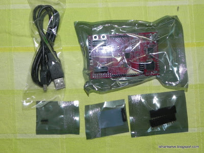
This post I am going to explain how I went about decoding / hacking a COTS Ultrasonic Car Parking Sensor. This project idea primarily stemmed out of sheer curiosity after reading a similar post at
MP3Car.com. The the original hack was done by one of the forum members at MP3car and he had explained his hack in great detail, surprisingly the author has withheld the firm ware for the micro controller and is available on sale only.
Being a electronics enthusiast with decent programming skills, I decided to venture in recreating this hack and most importantly release the code in open source.
I sourced the a parking sensor from
ebay.in. And as the luck would have had it, I got the same parking system as the original author had.
Devel Board:
Home made PIC 18f4550 devel board with a 20MHz crystal.
Theory of operation:
The parking sensor communicates with the display console over an rf link. In my case I screwed up my RF receiver in the display console due to hurry and 'bad engineering practises'. So the only option left was hard wiring to my micro-controller dev. board.
Decoding the Communication Protocol
The system uses PWM (Pulse Width Modulation) to communicate. The shorter pulse in logic 0 and the longer pulse is logic 1.
Since I have no high end development tools at my home to estimate pulse width, I used my devel. board to estimate the pulse width. I used a slightly modified EX_CCPMP.C example available in CCS compiler library to estimate the pulse width. Following is the code
1:  #include <18F4550.H>
2:  #fuses HSPLL, PLL5, CPUDIV1, NOWDT, PUT, BROWNOUT, NOLVP
3:  #use delay(clock=48000000)
4:  #use rs232(baud=19200, xmit=PIN_C6, rcv=PIN_C7)
5:  long rise,fall,pulse_width;
6:  #int_ccp2
7:  void isr()
8:  {
9:    rise = CCP_1;
10:    fall = CCP_2;
11:    pulse_width = fall - rise;
12:  }
13:  //short Pin 17 and 16 on microcontroller to use CCP1 and CCP2
14:  void main()
15:  {
16:    printf("\n\rHigh time\n\r");
17:    setup_ccp1(CCP_CAPTURE_RE);  // Configure CCP1 to capture rise
18:    setup_ccp2(CCP_CAPTURE_FE);  // Configure CCP2 to capture fall
19:    setup_timer_1(T1_INTERNAL);  // Start timer 1
20:    enable_interrupts(INT_CCP2);  // Setup interrupt on falling edge
21:    enable_interrupts(GLOBAL);
22:    while(TRUE) {
23:     printf("\n\r%lu us ", pulse_width);
24:    }
25:  }
Using this I realised that the pulse widths were
3599 us -> Logic Zero
7198 us -> Logic One.
They might be wrong due to wrong setup of CCP module (due to my ignorance). But it doesn't matter till the time you get two distinct pulse widths.
Once this step was over the next step was to make a bit stream out of this pulse width outputs. I slightly modified the above code to dump the bit stream on a serial console
1:  #include <18F4550.H>
2:  #fuses HSPLL, PLL5, CPUDIV1, NOWDT, PUT, BROWNOUT, NOLVP
3:  #use delay(clock=48000000)
4:  #use rs232(baud=9600, xmit=PIN_C6, rcv=PIN_C7)
5:  int bit_val;short flag;
6:  long rise,fall,pulse_width;
7:  #int_ccp2
8:  void isr()
9:  {
10:   rise = CCP_1;
11:    fall = CCP_2;
12:    pulse_width = fall - rise;
13:    bit_val=3;
14:  if (pulse_width <=3600 && pulse_width >=3598) {
15:    bit_val=0;
16:    }
17:  if (pulse_width <=7200 && pulse_width >=7197) {
18:    bit_val=1;
19:    }
20:  }
21:  void main()
22:  {
23:    printf("\n\rPulse Width:\n\r");
24:    setup_ccp1(CCP_CAPTURE_RE);  // Configure CCP1 to capture rise
25:    setup_ccp2(CCP_CAPTURE_FE);  // Configure CCP2 to capture fall
26:    setup_timer_1(T1_INTERNAL);  // Start timer 1
27:    enable_interrupts(INT_CCP2);  // Setup interrupt on falling edge
28:    enable_interrupts(GLOBAL);
29:    while(TRUE) {
30:     if (bit_val<=1){
31:     //printf("\n\r%lu us ", pulse_width );
32:     printf("%u", bit_val);
33:       bit_val=4;
34:     }
35:    }
36:  }
This was the dump I got on the serial port
 Pulse Width:
 1101001011101111000100001101001011101111000100001110000111101111000100001110000100000
00011111111110000111110111100010000110000110010011111011000111100001110111100010000111
10000001010011101011011010010111011110001000011010010000000001111111111100001000000001
11111111110000100000000111111111100001100100111110110001100001100100111110110001111000
00010100111010110111100000010100111010110110100100000000011111111110100100000000011111
11111100001000000001111111111100001000000001111111111000011001001111101100011000011001
00111110110001111000000101001110101101111000000101001110101101101001000000000111111111
10100100000000011111111111000010000000011111111111000010000000011111111110000110010011
11101100011000011001001111101100011110000001010011101011011110000001010011101011011010
01000000000111111111101001000000000111111111110000100000000111111111110000100000000111
11111110000110010011111011000110000110010011111011000111100000010100111010110111100000
01010011101011011010010000000001111111111010010000000001111111111100001000000001111111
11110000100000000111111111100001100100111110110001100001100100111110110001111000000101
00111010110111100000010100111010110110100100000000011111111110100100000000011111111111
00001000000001111111111100001000000001111111111000011001001111101100011000011001010001
10101111111000000101001110101101111000000101001110101101101001000000000111111111101001
00000000011111111111000010000000011111111111000010000000011111111110000110010100011010
11111000011001001111101100011110000001010011101011011110000001010011101011011010010000
00000111111111101001000000000111111111110000100000000111111111110000100000000111111111
10000110010011111011000110000110010011111011000111100000010100111010110111100000010100
Bit Structure
Total data packet of each sensor consists of 24 bits (3bytes x8)
The first byte is the sensor address and consists of 2 nibbles which are complementary of each other (1111 0000).
The second byte is the complement of third byte. and third byte contains the distance data (in centimeters)
Sensors are numbered as 0,1,2,3 so in the binary representation along with the nibble part they become:-
A=11110000 (1111 0000)
B=11010010 (1101 0010)
C=11100001 (1110 0001)
D=11000011 (1100 0011)
Another hidden thing (which the original author did not mention). Each data frame is transmitted twice and the readings are not repeated. So the bit stream is like AABBCCDDAABBCCDD........
Once we are done till here... the last step is only to write the code to search the bit stream for those golden characters mentioned above.
The logic is as follows
- Read the bits and load them in a buffer using left shift.
- Continuously read the buffer till you encounter sensor address.. i.e value of buffer = sensor address.
- Empty the buffer and read next 8 bits (distance nibblebits)
- Distance in centimeters is complement of the 2nd bit.
- Reset all flags and variables to zero
- Implement above in a code.
Here is the final code... needs much improvement
1:  /*
2:  <Automotive Ultrasonic Car Parking Sensor Protocol Decoder>
3:    Copyright (C) <2011> <Ishan Anant Karve>
4:    This program is free software: you can redistribute it and/or modify
5:    it under the terms of the GNU General Public License as published by
6:    the Free Software Foundation, either version 3 of the License, or
7:    (at your option) any later version.
8:    This program is distributed in the hope that it will be useful,
9:    but WITHOUT ANY WARRANTY; without even the implied warranty of
10:    MERCHANTABILITY or FITNESS FOR A PARTICULAR PURPOSE. See the
11:    GNU General Public License for more details.
12:    Visit <http://www.gnu.org/licenses/> for terms and conditions.
13:  /*
14:  #include <18F4550.H>
15:  #fuses HSPLL, PLL5, CPUDIV1, NOWDT, PUT, BROWNOUT, NOLVP
16:  #use delay(clock=48000000)
17:  #use rs232(baud=19200, xmit=PIN_C6, rcv=PIN_C7)
18:  #define SEN_A 0b11110000
19:  #define SEN_B 0b11010010
20:  #define SEN_C 0b11100001
21:  #define SEN_D 0b11000011
22:  int bit_val;int count;
23:  short sensor_ready,nibble_byte_ready, dist_byte_ready; //flags for correspond to 03 bytes of each sensor data
24:  int sensor, nibble_byte; byte dist_byte;
25:  long rise,fall,pulse_width;int16 temp;
26:  #int_ccp2
27:  void isr()
28:  {
29:   rise = CCP_1;
30:    fall = CCP_2;
31:    pulse_width = fall - rise;
32:  bit_val=2;
33:  if (pulse_width <=3600 && pulse_width >=3598) {
34:   bit_val=0; count++;shift_left(&temp,1,bit_val);
35:   }
36:  if (pulse_width <=7200 && pulse_width >=7197) {
37:   bit_val=1; count++;shift_left(&temp,1,bit_val);
38:   }
39:   if (temp==SEN_A){sensor=1;sensor_ready=1;count=0;nibble_byte_ready=0; dist_byte_ready=0;nibble_byte=0;dist_byte=0;temp=0;}
40:   if (temp==SEN_B){sensor=2;sensor_ready=1;count=0;nibble_byte_ready=0; dist_byte_ready=0;nibble_byte=0;dist_byte=0;temp=0;}
41:   if (temp==SEN_C){sensor=3;sensor_ready=1;count=0;nibble_byte_ready=0; dist_byte_ready=0;nibble_byte=0;dist_byte=0;temp=0;}
42:   if (temp==SEN_D){sensor=4;sensor_ready=1;count=0;nibble_byte_ready=0; dist_byte_ready=0;nibble_byte=0;dist_byte=0;temp=0;}
43:  }
44:  void main()
45:  {   count=0;temp=0;bit_val=2;
46:   //init all flags
47:    sensor_ready=0;nibble_byte_ready=0; dist_byte_ready=0;
48:   //init all vars
49:   sensor=0;nibble_byte=0;dist_byte=0;
50:   printf("\n\rPulse Width:\n\r");
51:     setup_ccp1(CCP_CAPTURE_RE);  // Configure CCP1 to capture rise
52:     setup_ccp2(CCP_CAPTURE_FE);  // Configure CCP2 to capture fall
53:     setup_timer_1(T1_INTERNAL);  // Start timer 1
54:     enable_interrupts(INT_CCP2);  // Setup interrupt on falling edge
55:     enable_interrupts(GLOBAL);
56:     while(TRUE) {
57:     if (sensor_ready && count==16){
58:     nibble_byte=make8(temp,0); dist_byte=~nibble_byte; //there is some problem in reading the dist_byte .. so the dirty solution
59:     printf("%u-> %u, %u, %Lu  ", sensor,nibble_byte,dist_byte,temp);
60:     if (sensor==4){printf("\r");}
61:     sensor=0;sensor_ready=0;count=0;nibble_byte_ready=0; dist_byte_ready=0;nibble_byte=0;dist_byte=0;temp=0;
62:    }
63:    }
64:  }
Ok guys this is the code to be compiled and flashed in your microcontroller.
 /*
 Copyright 2011 Ishan Anant Karve, India. All rights reserved.
 Redistribution and use in source and binary forms, with or without modification, are
 permitted provided that the following conditions are met:
   1. Redistributions of source code must retain the above copyright notice, this list of
    conditions and the following disclaimer.
   2. Redistributions in binary form must reproduce the above copyright notice, this list
    of conditions and the following disclaimer in the documentation and/or other materials
    provided with the distribution.
 THIS SOFTWARE IS PROVIDED BY ISHAN ANANT KARVE ``AS IS'' AND ANY EXPRESS OR IMPLIED
 WARRANTIES, INCLUDING, BUT NOT LIMITED TO, THE IMPLIED WARRANTIES OF MERCHANTABILITY AND
 FITNESS FOR A PARTICULAR PURPOSE ARE DISCLAIMED. IN NO EVENT SHALL <COPYRIGHT HOLDER> OR
 CONTRIBUTORS BE LIABLE FOR ANY DIRECT, INDIRECT, INCIDENTAL, SPECIAL, EXEMPLARY, OR
 CONSEQUENTIAL DAMAGES (INCLUDING, BUT NOT LIMITED TO, PROCUREMENT OF SUBSTITUTE GOODS OR
 SERVICES; LOSS OF USE, DATA, OR PROFITS; OR BUSINESS INTERRUPTION) HOWEVER CAUSED AND ON
 ANY THEORY OF LIABILITY, WHETHER IN CONTRACT, STRICT LIABILITY, OR TORT (INCLUDING
 NEGLIGENCE OR OTHERWISE) ARISING IN ANY WAY OUT OF THE USE OF THIS SOFTWARE, EVEN IF
 ADVISED OF THE POSSIBILITY OF SUCH DAMAGE.
 The views and conclusions contained in the software and documentation are those of the
 authors and should not be interpreted as representing official policies, either expressed
 */
 #include <18F4550.h>
 #fuses HSPLL,NOWDT,NOPROTECT,NOLVP,NODEBUG,USBDIV,PLL5,CPUDIV1,VREGEN
 #use delay(clock=48000000)
 #use rs232(baud=19200, xmit=PIN_C6, rcv=PIN_C7)
 #DEFINE USB_HID_DEVICE TRUE
 #define USB_EP1_TX_ENABLE USB_ENABLE_INTERRUPT  //turn on EP1 for IN bulk/interrupt transfers
 #define USB_EP1_TX_SIZE  8 //allocate 8 bytes in the hardware for transmission
 #define USB_EP1_RX_ENABLE USB_ENABLE_INTERRUPT  //turn on EP1 for OUT bulk/interrupt transfers
 #define USB_EP1_RX_SIZE  8 //allocate 8 bytes in the hardware for reception
 #define RAND_MAX 200
 #define SEN_A     0b11110000 //SENSOR A Address
 #define SEN_B     0b11010010     //SENSOR B Address
 #define SEN_C     0b11100001     //SENSOR C Address
 #define SEN_D     0b11000011     //SENSOR D Address
 //change USB descriptors for custom use
 #include <stdlib.h>           //required for rand() function
 #include <pic18_usb.h>  //Microchip 18Fxx5x hardware layer for usb.c
 #include <usb_desc_hid.h>     //USB Configuration and Device descriptors for this UBS device
 #include <usb.c>    //handles usb setup tokens and get descriptor reports
 short tx_flag;
 int bit_val;int count;
 short sensor_ready; //flags for correspond to 03 bytes of each sensor data
 int sensor,Dist_A,Dist_B,Dist_C,Dist_D, nibble_byte,dist_byte;
 short BUZZER;
 long rise,fall,pulse_width;int16 temp;
 #int_ccp2
 void isr()
 {
  rise = CCP_1;
   fall = CCP_2;
   pulse_width = fall - rise;
 bit_val=2;
 if (pulse_width <=3600 && pulse_width >=3598) {
      bit_val=0; count++;shift_left(&temp,1,bit_val);
      }
 if (pulse_width <=7200 && pulse_width >=7197) {
      bit_val=1; count++;shift_left(&temp,1,bit_val);
      }
      if (temp==SEN_A){sensor=1;sensor_ready=1;count=0;nibble_byte=0;dist_byte=0;temp=0;} //distance DIST_A purposely not set to zero
      if (temp==SEN_B){sensor=2;sensor_ready=1;count=0;nibble_byte=0;dist_byte=0;temp=0;}
      if (temp==SEN_C){sensor=3;sensor_ready=1;count=0;nibble_byte=0;dist_byte=0;temp=0;}
      if (temp==SEN_D){sensor=4;sensor_ready=1;count=0;nibble_byte=0;dist_byte=0;temp=0;}
 }
 void main() {
 int8 out_data[20];
 int8 in_data[2];
 int8 send_timer=0;
 count=0;temp=0;bit_val=2;tx_flag=0;
 sensor=0;sensor_ready=0;count=0;nibble_byte=0;dist_byte=0;Dist_A=0;Dist_B=0;Dist_C=0;Dist_D=0;
 //SETUP INTERRUPTS
 setup_ccp1(CCP_CAPTURE_RE);  // Configure CCP1 to capture rise
 setup_ccp2(CCP_CAPTURE_FE);  // Configure CCP2 to capture fall
 setup_timer_1(T1_INTERNAL);  // Start timer 1
 enable_interrupts(INT_CCP2);  // Setup interrupt on falling edge
 enable_interrupts(GLOBAL);
 delay_ms(1000);
 printf("\r\n\nParking Sensor");
 usb_init_cs();
      while (TRUE) {
   usb_task();
           if (sensor_ready && count==16){
                nibble_byte=make8(temp,0); dist_byte=~nibble_byte;
                switch (sensor) {
                  case 1:Dist_A=dist_byte; //Set data for Sensor A
                break;
                  case 2:Dist_B=dist_byte; //Set data for Sensor B
                break;
                  case 3:Dist_C=dist_byte; //Set data for Sensor C
                break;
                  case 4:Dist_D=dist_byte; //Set data for Sensor D
                break;
              }
                //printf("%u --> %u\n\r"sensor,dist_byte); //for debug purposes
                //reset all variables
                sensor=0;sensor_ready=0;count=0;nibble_byte=0;dist_byte=0;temp=0;
           }
    if (usb_enumerated()) {
      if (!send_timer) {
       send_timer=250;
       out_data[0]=Dist_A;
       out_data[1]=Dist_B;
       out_data[2]=Dist_C;
       out_data[3]=Dist_D;
       out_data[4]=0;
            if (tx_flag){tx_flag=0;
                 if (usb_put_packet(1, out_data,5, USB_DTS_TOGGLE)){
                   //printf("\r\n<-- Sending 2 bytes: 0x%X 0x%X 0x%X 0x%X 0x%X", out_data[0], out_data[1], out_data[2], out_data[3], out_data[4]);
                          //printf("\r\n<-- Sending 2 bytes: %u %u %u %u %u", out_data[0], out_data[1], out_data[2], out_data[3], out_data[4]);// for debug purposes
                          }
                }
                }
      if (usb_kbhit(1)) {
       usb_get_packet(1, in_data, 2);
       {
                //printf("\r\n--> Received data: 0x%X 0x%X",in_data[0],in_data[1]);//for debug purposes
                }
       if (in_data[0]==0x20) {tx_flag=1;}
     }
      send_timer--;
      delay_ms(1);
    }
   }
 }
Thats all....... Will post the circuit schematic shortly... Thanks for reading.