I generally tend to spend a lot of time working on my PC, not realising what the time it is. A bit of ponder made me realise that I did not have a clock in my room (Thats the Xcuse!!).. Clock in the deskbar/panel/Taskbar is so Uncool.. So I decided to make a custom made digital clock.
An immediate rummaging of my component inventory revealed that I had the necessary gear to accomplish the task..
So here's the part list:-
- PIC 16F628A
- RTC DS1302
- HD44780 Compatible 20x4 LCD Display
- Rotary/Quadrature Encoder
- Resistors
- Capacitors
- Diodes
- LM7805
- Prototyping Board
- Trimpot 10K
- Patience
Development Platform: MPLAB using CCS C Compiler and a PICKIT3 Programmer/Debugger.
Cool Factor: No Buttons for Menu. Only a single Quadrature Rotary Encoder accomplishes all required menu operations.
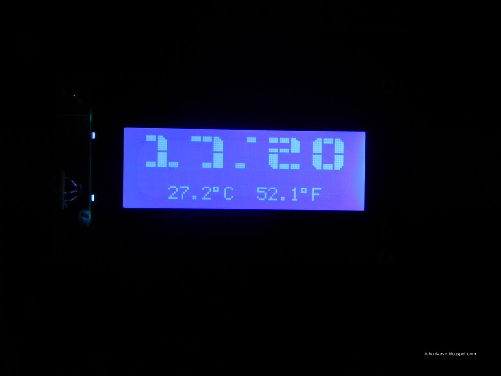
End Product
 |
| End Product poorly mounted ! |
 |
| Time is 17:19 |
 |
| Still working after three minutes...... Gr8! |
large_lcd.h
#include <16f628a.h>
#fuses INTRC_IO, NOWDT, BROWNOUT,  NOLVP
#use delay (internal=4MHz)

//=======================
#include "flex_lcd.h"
#include "ds1302.h"
#include "ds18b20.h"
//===================================

//========================================MENU FLAGS==========================================
//menu flags/value. default state/value of all flags is 0
short blink_flag=0;
int menu_digit_flag=0;    //1 is hour; 2 is minute ;0 is normal modde
int clock_mode=0;//0 is normal ; 1 is menu mode (blinking display); 2 is edit mode
//============================================================================================
byte hour,minute,second,day,month,year,weekday;
 int8 b1, b2, b3, b4;
byte HH,MM;

//for rotary encoder
#define CH_A    PIN_A4
#define CH_B    PIN_A3
#define button    PIN_A2

int encoder0Pos = 0;
int encoder0PinALast = 0;
int n = 0;

void read_encoder(){
int MAX=9; int MIN=0;
if (menu_digit_flag==1){MAX=23;}//hours
if (menu_digit_flag==2) {MAX=59;}//minutes
n = input(CH_B);
   if ((encoder0PinALast == 0) && (n == 1)) {
    lcd_gotoxy(1,1);
    printf(lcd_putc,"                   ");
    lcd_gotoxy(1,2);
    printf(lcd_putc,"                   ");

     if (input(CH_B) == 0) {
       encoder0Pos--;
     } else {
       encoder0Pos++;
     }

    }
   encoder0PinALast = n;


if(encoder0Pos>MAX){encoder0Pos=0;}
if(encoder0Pos<MIN){encoder0Pos=0;}


}
void display_number(int num){
int digit1,digit2;
if (num<=99){
digit1=num/10;
digit2=num%10;
show_num(digit1);
x_pos_state=x_pos_state+4;
show_num(digit2);
x_pos_state=1;
}
}


adj_hour()
{
x_pos_state=2;
read_encoder();
HH=encoder0Pos;
display_number(HH);

}


adj_minute()
{
x_pos_state=13;
read_encoder();
MM=encoder0Pos;
display_number(MM);

}

set_time(){
//set rtc time
rtc_set_datetime(day,month,year,weekday,HH,MM);
//reset all flags to normal state

}
//=============================
#include <button_interrupt.c>
//=============================
void main()
{


    // Setup timer2 to int every 1ms
  setup_timer_2(T2_DIV_BY_4,125,5);
  enable_interrupts(INT_TIMER2);
  enable_interrupts(GLOBAL);

  // Start counting now
  Miliseconds = 0;


// The lcd_init() function should always be called once,
// near the start of your program.
lcd_init();
lcd_load_custom_chars();
rtc_init();

// Clear the LCD.
printf(lcd_putc, "\f");
delay_ms(250);

while(1)
{


    if ((clock_mode==2) && (menu_digit_flag==1)){adj_hour();}
    if ((clock_mode==2) && (menu_digit_flag==2)){adj_minute();}
if (clock_mode<=1){
rtc_get_time( hour, minute, second );
ResetDS1820();
cDataOut = DS1820_SKIP_ROM;
WriteDS1820();
cDataOut = DS1820_CONVERT_T;
WriteDS1820();
WaitForConversion();
ResetDS1820();
cDataOut = DS1820_SKIP_ROM;
WriteDS1820();
cDataOut = DS1820_READ_SCRATCHPAD;
WriteDS1820();
ReadDS1820();
iTemperature = iDataIn / 2;
lcd_gotoxy(4,4);
printf ( lcd_putc, "%3.1w%cC  %3.1w%cF   ", iTemperature, DEGREE_SYM, ( ( 9 * iTemperature ) / 5 ) + 32, DEGREE_SYM  );

x_pos_state=2;
rtc_get_time( hour, minute, second );
b1=hour;
b2=minute;
if (b3!=b1){clearnumber(2);clearnumber(4);b3=b1;}
if (b4!=b2){clearnumber(13);clearnumber(17);b4=b2;}
display_number(hour);
x_pos_state=10;
if (second%2==0){custom_dah();clearnumber(10);}
if (second%2==1){custom_dit();}
x_pos_state=13;
display_number(minute);
}
System_Tick();
Switch_Tasks();


 }

}
flex_lcd.h (modified for large digits)
// Flex_LCD420.c

// These pins are for my Microchip PicDem2-Plus board,
// which I used to test this driver.
// An external 20x4 LCD is connected to these pins.
// Change these pins to match your own board's connections.

#define LCD_DB4   PIN_A1
#define LCD_DB5   PIN_A0
#define LCD_DB6   PIN_A7
#define LCD_DB7   PIN_A6

#define LCD_RS    PIN_B2
#define LCD_RW    PIN_B1
#define LCD_E     PIN_B0

/*
// To prove that the driver can be used with random
// pins, I also tested it with these pins:
#define LCD_DB4   PIN_D4
#define LCD_DB5   PIN_B1
#define LCD_DB6   PIN_C5
#define LCD_DB7   PIN_B5

#define LCD_RS    PIN_E2
#define LCD_RW    PIN_B2
#define LCD_E     PIN_D6
*/

// If you want only a 6-pin interface to your LCD, then
// connect the R/W pin on the LCD to ground, and comment
// out the following line.  Doing so will save one PIC
// pin, but at the cost of losing the ability to read from
// the LCD.  It also makes the write time a little longer
// because a static delay must be used, instead of polling
// the LCD's busy bit.  Normally a 6-pin interface is only
// used if you are running out of PIC pins, and you need
// to use as few as possible for the LCD.
//#define USE_RW_PIN   0


// These are the line addresses for most 4x20 LCDs.
#define LCD_LINE_1_ADDRESS 0x00
#define LCD_LINE_2_ADDRESS 0x40
#define LCD_LINE_3_ADDRESS 0x14
#define LCD_LINE_4_ADDRESS 0x54

// These are the line addresses for LCD's which use
// the Hitachi HD66712U controller chip.
/*
#define LCD_LINE_1_ADDRESS 0x00
#define LCD_LINE_2_ADDRESS 0x20
#define LCD_LINE_3_ADDRESS 0x40
#define LCD_LINE_4_ADDRESS 0x60
*/


//========================================

#define lcd_type 2   // 0=5x7, 1=5x10, 2=2 lines(or more)

int8 lcd_line;

int x_pos_state=1;


int8 const LCD_INIT_STRING[4] =
{
 0x20 | (lcd_type << 2),  // Set mode: 4-bit, 2+ lines, 5x8 dots
 0xc,                     // Display on
 1,                       // Clear display
 6                        // Increment cursor
 };


//-------------------------------------
void lcd_send_nibble(int8 nibble)
{
// Note:  !! converts an integer expression
// to a boolean (1 or 0).
 output_bit(LCD_DB4, !!(nibble & 1));
 output_bit(LCD_DB5, !!(nibble & 2));
 output_bit(LCD_DB6, !!(nibble & 4));
 output_bit(LCD_DB7, !!(nibble & 8));

 delay_cycles(1);
 output_high(LCD_E);
 delay_us(2);
 output_low(LCD_E);
}

//-----------------------------------
// This sub-routine is only called by lcd_read_byte().
// It's not a stand-alone routine.  For example, the
// R/W signal is set high by lcd_read_byte() before
// this routine is called.

#ifdef USE_RW_PIN
int8 lcd_read_nibble(void)
{
int8 retval;
// Create bit variables so that we can easily set
// individual bits in the retval variable.
#bit retval_0 = retval.0
#bit retval_1 = retval.1
#bit retval_2 = retval.2
#bit retval_3 = retval.3

retval = 0;

output_high(LCD_E);
delay_us(1);

retval_0 = input(LCD_DB4);
retval_1 = input(LCD_DB5);
retval_2 = input(LCD_DB6);
retval_3 = input(LCD_DB7);

output_low(LCD_E);
delay_us(1);

return(retval);
}
#endif

//---------------------------------------
// Read a byte from the LCD and return it.

#ifdef USE_RW_PIN
int8 lcd_read_byte(void)
{
int8 low;
int8 high;

output_high(LCD_RW);
delay_cycles(1);

high = lcd_read_nibble();

low = lcd_read_nibble();

return( (high<<4) | low);
}
#endif

//----------------------------------------
// Send a byte to the LCD.
void lcd_send_byte(int8 address, int8 n)
{
output_low(LCD_RS);

#ifdef USE_RW_PIN
while(bit_test(lcd_read_byte(),7)) ;
#else
delay_us(60);
#endif

if(address)
   output_high(LCD_RS);
else
   output_low(LCD_RS);

 delay_cycles(1);

#ifdef USE_RW_PIN
output_low(LCD_RW);
delay_cycles(1);
#endif

output_low(LCD_E);

lcd_send_nibble(n >> 4);
lcd_send_nibble(n & 0xf);
}
//----------------------------

void lcd_init(void)
{
int8 i;

lcd_line = 1;

output_low(LCD_RS);

#ifdef USE_RW_PIN
output_low(LCD_RW);
#endif

output_low(LCD_E);

// Some LCDs require 15 ms minimum delay after
// power-up.  Others require 30 ms.  I'm going
// to set it to 35 ms, so it should work with
// all of them.
delay_ms(35);

for(i=0 ;i < 3; i++)
   {
    lcd_send_nibble(0x03);
    delay_ms(5);
   }

lcd_send_nibble(0x02);

for(i=0; i < sizeof(LCD_INIT_STRING); i++)
   {
    lcd_send_byte(0, LCD_INIT_STRING[i]);

    // If the R/W signal is not used, then
    // the busy bit can't be polled.  One of
    // the init commands takes longer than
    // the hard-coded delay of 50 us, so in
    // that case, lets just do a 5 ms delay
    // after all four of them.
    #ifndef USE_RW_PIN
    delay_ms(5);
    #endif
   }

}

//----------------------------

void lcd_gotoxy(int8 x, int8 y)
{
int8 address;


switch(y)
  {
   case 1:
     address = LCD_LINE_1_ADDRESS;
     break;

   case 2:
     address = LCD_LINE_2_ADDRESS;
     break;

   case 3:
     address = LCD_LINE_3_ADDRESS;
     break;

   case 4:
     address = LCD_LINE_4_ADDRESS;
     break;

   default:
     address = LCD_LINE_1_ADDRESS;
     break;

  }

address += x-1;
lcd_send_byte(0, 0x80 | address);
}
//----------------------------


//-----------------------------
void lcd_putc(char c)
{
 switch(c)
   {
    case '\f':
      lcd_send_byte(0,1);
      lcd_line = 1;
    //  delay_ms(2);
      break;

    case '\n':
       lcd_gotoxy(1, ++lcd_line);
       break;

    case '\b':
       lcd_send_byte(0,0x10);
       break;

    default:
       lcd_send_byte(1,c);
       break;
   }
}

//------------------------------
#ifdef USE_RW_PIN
char lcd_getc(int8 x, int8 y)
{
char value;

lcd_gotoxy(x,y);

// Wait until busy flag is low.
while(bit_test(lcd_read_byte(),7));

output_high(LCD_RS);
value = lcd_read_byte();
output_low(LCD_RS);

return(value);
}
#endif

const int8 lcd_custom_chars[] =
{
  0b00000111,
  0b00001111,
  0b00011111,
  0b00011111,
  0b00011111,
  0b00011111,
  0b00011111,
  0b00011111,

  0b00011111,
  0b00011111,
  0b00011111,
  0b00000000,
  0b00000000,
  0b00000000,
  0b00000000,
  0b00000000,

  0b00011100,
  0b00011110,
  0b00011111,
  0b00011111,
  0b00011111,
  0b00011111,
  0b00011111,
  0b00011111,

  0b00011111,
  0b00011111,
  0b00011111,
  0b00011111,
  0b00011111,
  0b00011111,
  0b00001111,
  0b00000111,

  0b00000000,
  0b00000000,
  0b00000000,
  0b00000000,
  0b00000000,
  0b00011111,
  0b00011111,
  0b00011111,

  0b00011111,
  0b00011111,
  0b00011111,
  0b00011111,
  0b00011111,
  0b00011111,
  0b00011110,
  0b00011100,

  0b00011111,
  0b00011111,
  0b00011111,
  0b00000000,
  0b00000000,
  0b00000000,
  0b00011111,
  0b00011111,

  0b00011111,
  0b00011111,
  0b00011111,
  0b00011111,
  0b00011111,
  0b00011111,
  0b00011111,
  0b00011111,
};

void lcd_load_custom_chars(void)
{
int8 i;

// Set address counter pointing to CGRAM address 0.
lcd_send_byte(0, 0x40);

// Load custom lcd character data into CGRAM.
// It can only hold a maximum of 8 custom characters.
for(i = 0; i < sizeof(lcd_custom_chars); i++)
   {
    lcd_send_byte(1, lcd_custom_chars[i]);
   }

// Set address counter pointing back to the DDRAM.
lcd_send_byte(0, 0x80);
}

void custom0()
{ // uses segments to build the number 0
  lcd_gotoxy(x_pos_state+0,1); // set cursor to column 0, line 0 (first row)
  lcd_putc(0);  // call each segment to create
  lcd_putc(1);  // top half of the number
  lcd_putc(2);
  lcd_gotoxy(x_pos_state+0, 2); // set cursor to colum 0, line 1 (second row)
  lcd_putc(3);  // call each segment to create
  lcd_putc(4);  // bottom half of the number
  lcd_putc(5);
}

void custom1()
{
  lcd_gotoxy(x_pos_state+0,1);
  lcd_putc(1);
  lcd_putc(2);
  lcd_gotoxy(x_pos_state+0,2);
  lcd_putc(4);
  lcd_putc(7);
  lcd_putc(4);
}

void custom2()
{
  lcd_gotoxy(x_pos_state+0,1);
  lcd_putc(6);
  lcd_putc(6);
  lcd_putc(2);
  lcd_gotoxy(x_pos_state+0, 2);
  lcd_putc(3);
  lcd_putc(4);
  lcd_putc(4);
}

void custom3()
{
  lcd_gotoxy(x_pos_state+0,1);
  lcd_putc(6);
  lcd_putc(6);
  lcd_putc(2);
  lcd_gotoxy(x_pos_state+0, 2);
  lcd_putc(4);
  lcd_putc(4);
  lcd_putc(5);
}

void custom4()
{
  lcd_gotoxy(x_pos_state+0,1);
  lcd_putc(3);
  lcd_putc(4);
  lcd_putc(7);
  lcd_gotoxy(x_pos_state+2, 2);
  lcd_putc(7);
}

void custom5()
{
  lcd_gotoxy(x_pos_state+0,1);
  lcd_putc(3);
  lcd_putc(6);
  lcd_putc(6);
  lcd_gotoxy(x_pos_state+0, 2);
  lcd_putc(4);
  lcd_putc(4);
  lcd_putc(5);
}

void custom6()
{
  lcd_gotoxy(x_pos_state+0,1);
  lcd_putc(0);
  lcd_putc(6);
  lcd_putc(6);
  lcd_gotoxy(x_pos_state+0, 2);
  lcd_putc(3);
  lcd_putc(4);
  lcd_putc(5);
}

void custom7()
{
  lcd_gotoxy(x_pos_state+0,1);
  lcd_putc(1);
  lcd_putc(1);
  lcd_putc(2);
  lcd_gotoxy(x_pos_state+2, 2);
  lcd_putc(7);
}

void custom8()
{
  lcd_gotoxy(x_pos_state+0,1);
  lcd_putc(0);
  lcd_putc(6);
  lcd_putc(2);
  lcd_gotoxy(x_pos_state+0, 2);
  lcd_putc(3);
  lcd_putc(4);
  lcd_putc(5);
}

void custom9()
{
  lcd_gotoxy(x_pos_state+0,1);
  lcd_putc(0);
  lcd_putc(6);
  lcd_putc(2);
  lcd_gotoxy(x_pos_state+2, 2);
  lcd_putc(7);
}

void custom_dit(){
  lcd_gotoxy(x_pos_state+1,1);
  lcd_putc(1);
  lcd_gotoxy(x_pos_state+0,2);
  lcd_putc(4);
}


void custom_dah(){
  lcd_gotoxy(x_pos_state+0,1);
  lcd_putc(1);
  lcd_gotoxy(x_pos_state+1,2);
  lcd_putc(4);

}

void clearnumber(int m)
{ // clears the area the custom number is displayed in
 lcd_gotoxy(m,1);
 printf(lcd_putc,"   ");
 lcd_gotoxy(m,2);
 printf(lcd_putc,"   ");
 }


void show_num(int num){
if (num<=9){
switch (num) {
    case 0:custom0();
           break;
    case 1:custom1();
           break;
    case 2:custom2();
           break;
    case 3:custom3();
           break;
    case 4:custom4();
           break;
    case 5:custom5();
           break;
    case 6:custom6();
           break;
    case 7:custom7();
           break;
    case 8:custom8();
           break;
    case 9:custom9();
           break;

    }

}
}
ds18b20.h
#define DS1820_DATA_IN_PIN          PIN_B3
#define DS1820_SKIP_ROM             0xCC
#define DS1820_READ_SCRATCHPAD      0xBE
#define DS1820_CONVERT_T            0x44

void ResetDS1820 ( void );
void WriteDS1820 ( void );
void ReadDS1820 ( void );
void WaitForConversion ( void );

#define CLEAR_DISP  0x01
#define DEGREE_SYM  0xdf


static char cShiftBit,cDataOut;
static long iTemperature,iDataIn;


void ResetDS1820 ( void )
    {
    output_low ( DS1820_DATA_IN_PIN );         // low
    delay_us ( 480 );                               // reset pulse width
    output_float ( DS1820_DATA_IN_PIN );          // high
    delay_us ( 480 );                               // presence pulse width
    }

void WriteDS1820 ( void )             // ~70uS per bit
    {
    for ( cShiftBit = 1; cShiftBit <= 8; ++cShiftBit )
        {
        output_low ( DS1820_DATA_IN_PIN );
        delay_us ( 5 );
        output_bit ( DS1820_DATA_IN_PIN, shift_right ( &cDataOut, 1, 0 ) );
        delay_us ( 60 );
        output_float ( DS1820_DATA_IN_PIN );
        delay_us ( 5 );         // recovery time between slots
        }
    //delay_us ( 200 );           // ???
    }

void ReadDS1820 ( void )             // ~70uS per bit
    {
    iDataIn = 0;
    for ( cShiftBit = 1; cShiftBit <= 16; ++cShiftBit )
       {
       output_low ( DS1820_DATA_IN_PIN );
       delay_us ( 5 );
       output_float ( DS1820_DATA_IN_PIN );
       delay_us ( 5 );
       shift_right ( &iDataIn, 2, input ( DS1820_DATA_IN_PIN ) );   // sample bit
       delay_us ( 55 );         // includes recovery time between slots
       }
    ResetDS1820();              // terminate remainder of scratchpad register transmission
    }

void WaitForConversion ( void )             // ~70uS per bit
    {
    while ( TRUE )
       {
       output_low ( DS1820_DATA_IN_PIN );
       delay_us ( 5 );
       output_float ( DS1820_DATA_IN_PIN );
       delay_us ( 5 );
       if ( input ( DS1820_DATA_IN_PIN ) == 1 )   // sample bit
           {
           break;
           }
       delay_us ( 55 );         // includes recovery time between slots
       }
    }

![\includegraphics[scale=0.500000]{ckt8.1.1.ps}](http://www.ece.rice.edu/~jdw/243_lab8/img57.png)